
Air source heat pump unit and defrosting control method thereof

An air source heat pump and unit technology, applied in the field of heat exchange, can solve the problems of reduced heating time, freezing of heat exchanger, and affecting the normal use of the unit, so as to avoid damage and improve reliability

Pending Publication Date: 2019-03-29
SHANGHAI HIGHLY REALNEN ENVIRONMENTAL TECH
View PDF6 Cites 30 Cited by
  • Summary
  • Abstract
  • Description
  • Claims
  • Application Information

AI Technical Summary

Problems solved by technology

In the case of low temperature and low humidity, there will be frequent cases where the heat exchanger has no frost and the unit is running to defrost, which not only causes the water temperature to drop and cause large temperature fluctuations, but also consumes a lot of energy to re-raise the water temperature to the temperature before defrosting, and the effective heating time is greatly reduced. , more seriously, the system will be shut down due to high pressure, and even cause damage to the refrigeration cycle system
In order to avoid this situation, some designs extend the defrosting cycle and lower the exit temperature. However, in high-humidity and low-temperature environment areas, it is easy to cause incomplete defrosting. After several defrosting cycles, the heat exchanger will condense. Ice phenomenon, especially in low temperature rainy and snowy weather, is very easy to cause the heat exchanger to freeze and even the chassis to freeze, which seriously affects the normal use of the unit

Method used


Image

  • Air source heat pump unit and defrosting control method thereof
  • Air source heat pump unit and defrosting control method thereof
  • Air source heat pump unit and defrosting control method thereof

Examples


Embodiment

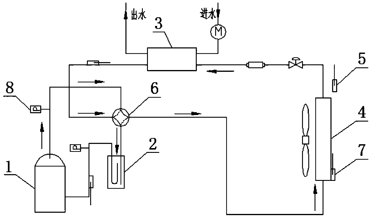
[0022] see figure 1 , the present invention provides an air source heat pump unit, including a compressor 1, a gas-liquid separator 2, a high-efficiency tank heat exchanger 3, a fin heat exchanger 4, an outdoor temperature and humidity sampling module 5, and a four-way reversing valve 6, The compressor 1 is connected to the gas-liquid separator 2 through the four-way reversing valve 6 to form a closed loop, and the finned heat exchanger 4 and the high-efficiency tank heat exchanger 3 are connected through the The four-way reversing valve 6 is connected in pipelines to form a closed loop, the fin heat exchanger 4 is provided with a temperature sensor 7, and the high-efficiency tank heat exchanger 3 is connected to the fin heat exchanger 4 An electronic expansion valve 8 is arranged on the pipeline, and a pressure sensor 9 is arranged on the pipeline connected between the compressor 1 and the four-way reversing valve 6 .

[0023] During normal heating, the high-temperature and ...


PUM


Abstract

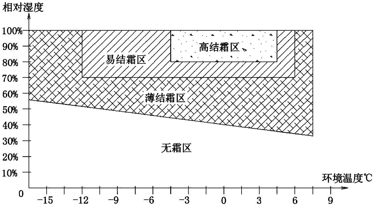
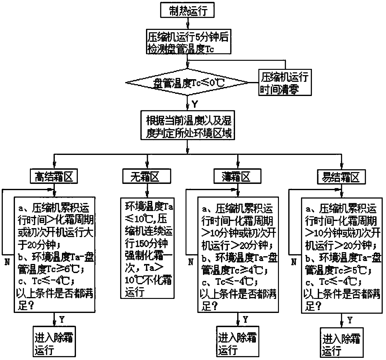
The invention discloses an air source heat pump unit and a defrosting control method thereof. The air source heat pump unit comprises a compressor, a gas-liquid separator, an high-efficient tank heatexchanger, a fin heat exchanger, an outdoor temperature and humidity sampling module and four-way reversing valves, the compressor and the gas-liquid separator are connected through the four-way reversing valve in a tube connecting mode, and the fin heat exchanger and the high-efficient tank heat exchanger are connected through the four-way reversing valve in a tube connecting mode; and the defrosting method of the unit comprises the steps that outdoor environment is divided into different environment regions according to the environment temperature and relative humidity, the region where theoperating environment is located is determined according to the current temperature and the humidity of the operating environment, and then the frosting detection and the defrosting treatment are carried out respectively according to the control logic of each region. According to the method, the frosting condition of the outdoor heat exchanger of the unit can be accurately detected under differentenvironment conditions, and different operations are carried out according to the actual frosting condition through a control system to achieve the effect that defrosting is carried out when the heatexchanger is frosted, heating is carried out when the heat exchanger is not frosted, defrosting is carried out according to the thickness of the frost, and the heating operation capability is fully ensured.

Description

technical field [0001] The invention relates to the technical field of heat exchange, in particular to an air source heat pump unit and a defrosting control method thereof. Background technique [0002] The air source heat pump cold (hot) water unit uses outdoor air as a heat source to exchange heat with the refrigerant, and then the refrigerant exchanges heat with the water medium to generate cold (hot) water, which is transported to the user's room for temperature regulation under the action of the water pump. of. Water circulates at the user end, and the water temperature is directly controlled. Compared with air conditioners, hot air fans and other temperature-adjusting products, it has incomparable advantages in terms of constant temperature capability, comfort, and energy saving. Because of these advantages, air source heat pump cold (hot) water units are widely used in the market, especially in recent years, with the promotion of national energy conservation and emis...

Claims


Application Information

Patent Timeline
Patent Type & Authority Applications(China)
IPC IPC(8): F25B13/00F25B41/00F25B47/02F24F11/42F24F11/64F24F11/70F24F110/12F24F110/22F25B41/40
CPCF24F11/42F24F11/64F24F11/70F25B13/00F25B47/02F24F2110/12F24F2110/22F25B41/40
Inventor 张贤硅沈洪刘冠军邱迎新
Owner SHANGHAI HIGHLY REALNEN ENVIRONMENTAL TECH
Learn More