Leakage current detecting device

A technology of leakage current detection and resistance, which is applied in the field of elevators, can solve the problems of unbalanced current, high cost, and out-of-synchronization of brake coils, etc., and achieve the effect of using fewer components, simple scheme, and high reliability

Pending Publication Date: 2019-03-29
TIANJIN KANGTU TECH CO LTD
View PDF0 Cites 2 Cited by
  • Summary
  • Abstract
  • Description
  • Claims
  • Application Information

AI Technical Summary

Problems solved by technology

The current on the two coils of the brake coil will be unbalanced. For example, in the first half cycle of AC: only the upper half of the coil at point M on L2 has current. This working method will cause the brake coils L1 and L2 to be out of sync, that is, one In the AC cycle, when L1 works through two wave currents, only a part of L2 works
When the elevator is running, it will cause the elevator to drag the brakes; when the elevator stops, when L2 continues to flow through the leakage point without passing through the freewheeling circuit, it will cause the brake to open a small gap and cause the elevator to slip.
Therefore, there is a need for a detection circuit and detection method that can solve the above problems. Because the existing detection methods in the market are basically realized by Hall sensors detecting the current between the brake coil and the earth and converting it into a voltage signal, the method is complicated and high cost

Method used


Image

  • Leakage current detecting device
  • Leakage current detecting device
  • Leakage current detecting device

Examples


Embodiment 1

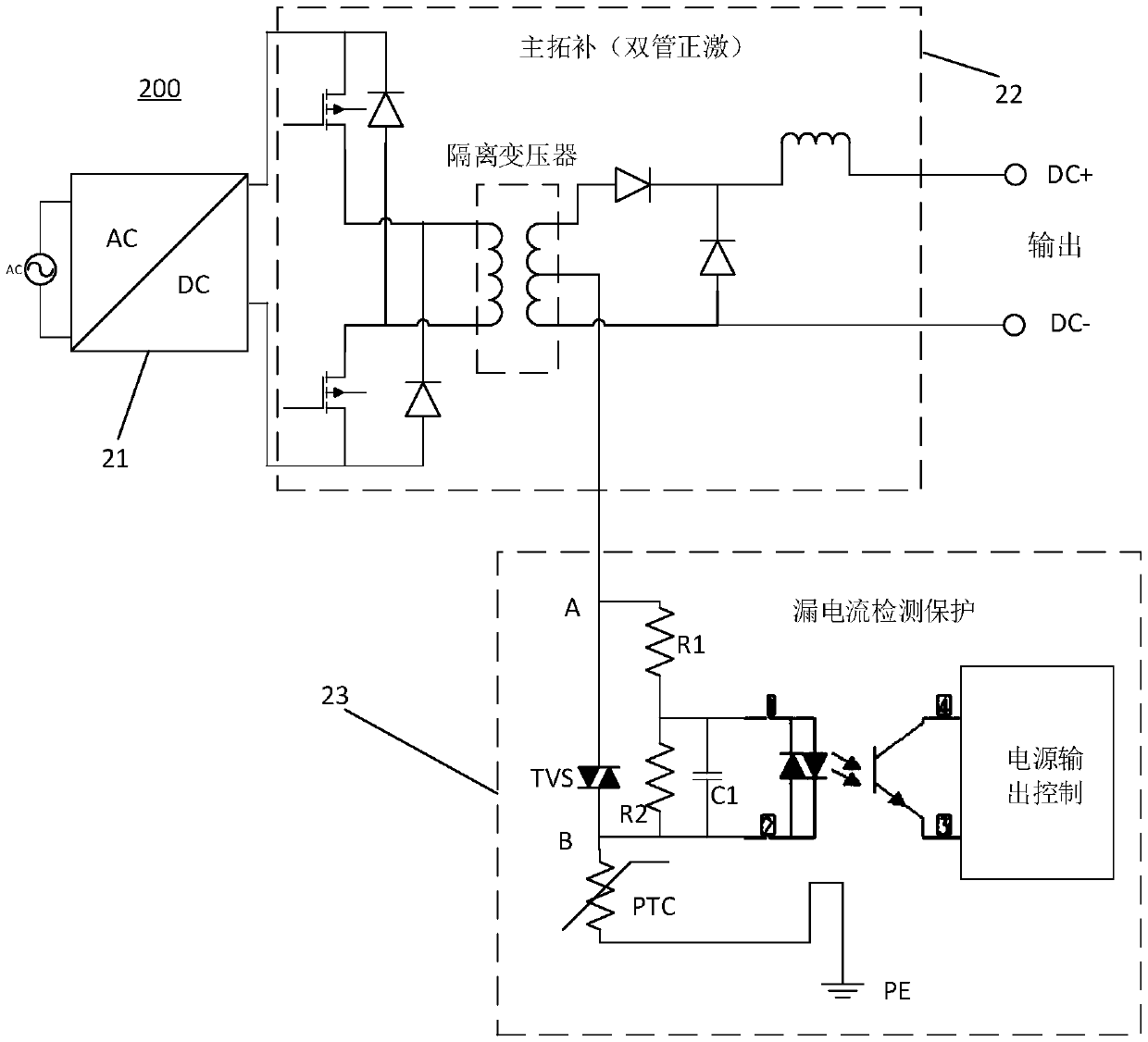
[0025] figure 2 is a schematic circuit diagram of a leakage current detection device provided by an embodiment of the present invention. see figure 2 , the leakage current detection device, including: the middle tap of the secondary winding of the isolation transformer (or the middle tap of the output filter inductor of the non-isolated topology), thermistor PTC, leakage current sampling resistor R2, adjusting resistor R1, bidirectional Transient suppression tube TVS, filter capacitor C1 and bidirectional optocoupler U1, the first end of the bidirectional transient suppression tube TVS is electrically connected to the middle tap of the secondary winding of the isolation transformer, and the second end of the bidirectional transient suppression tube TVS end is electrically connected with the first end of the thermistor PTC, the second end of the thermistor PTC is grounded, the first end of the adjusting resistor RI is connected with the first end of the bidirectional transie...

Embodiment 2

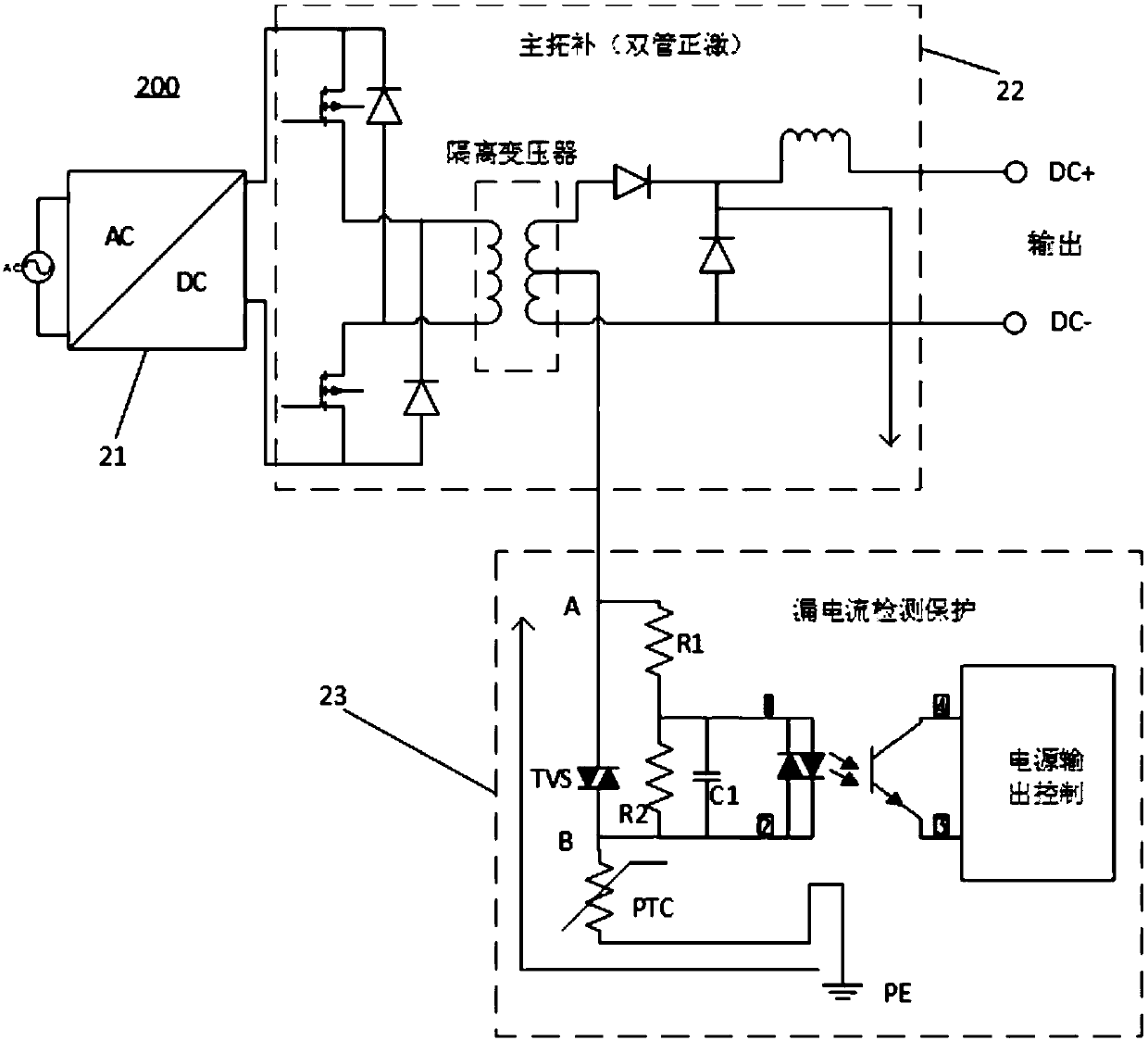
[0032] Figure 4 is a schematic circuit diagram of the leakage current detection device provided by Embodiment 2 of the present invention. This embodiment is optimized on the basis of the foregoing embodiments. Specifically, the leakage current detection device can also be added: a power output control unit, the power output control unit is electrically connected to the secondary side of the bidirectional optocoupler U1, and the power output control unit is used to The detection signal generated by the secondary side of the optocoupler U1 controls the on-off of the power supply.

[0033] When it is detected that the output of the integrated power supply leaks to the ground PE, the leakage detection signal is output in time to control the output of the integrated power supply. When the output part of the integrated power supply brake is leaking, the output of the integrated power supply can be controlled to stop the elevator and prevent the elevator from being dragged. On the...


PUM


Abstract

An embodiment of the invention discloses a leakage current detecting device. The device comprises an intermediate tap of a secondary winding of an isolation transformer, a thermistor PTC, a leakage current sampling resistor R2, a regulating resistor R1, a bidirectional transient voltage suppressor (TVS), a filter capacitor C1 and a bidirectional optocoupler U1. The first end of the bidirectional transient voltage suppressor (TVS) is electrically connected to the intermediate tap of the secondary winding of the isolation transformer, and the bidirectional transient voltage suppressor (TVS) is connected in series with the thermistor and grounded. The regulating resistor R1 is connected in series with the leakage current sampling resistor R2 and then connected in parallel with the bidirectional transient voltage suppressor (TVS), the second end of the filter capacitor C1 is electrically connected to the second end of the leakage current sampling resistor R2, the primary side of the bidirectional optocoupler U1 is connected to the filter capacitor C1 in parallel, and the secondary side of the bidirectional optocoupler U1 generates a detection signal. The leakage current detecting device has the advantages of low cost, simple solution, few devices, simple solution and high reliability.

Description

technical field [0001] The invention relates to the technical field of elevators, in particular to a leakage current detection device. Background technique [0002] On the one hand, in many old elevators, due to the long-term use of the brake coil and the aging of the coil, the insulation function is reduced, and there may be a fault phenomenon that the coil leaks to the earth PE; and when the leakage current does not reach the brake circuit When controlling the operating current of the air switch (generally 30mA, or the control air switch is faulty), the control air switch will not trip, which will further cause the elevator to drag the brakes or slip, resulting in safety hazards. [0003] figure 1 It is a schematic diagram of an elevator brake power supply circuit in the prior art. refer to figure 1 , the existing brake power supply circuit 100 includes a brake power supply circuit 11 , a freewheeling circuit 12 , and a brake coil 13 . During normal operation, when the...

Claims


Application Information

Patent Timeline
Patent Type & Authority Applications(China)
IPC IPC(8): G01R19/165G01R31/02
CPCG01R19/16571G01R31/50
Inventor 潘瑞敏
Owner TIANJIN KANGTU TECH CO LTD
Why Eureka
Try Eureka