Fiber cable fixing device

A cable fixing device and optical fiber technology, which is applied in the field of optical fiber cables, can solve problems such as poor practicability, wear and tear of optical fiber cables, swinging and offsetting of optical fiber cables, etc., and achieve the effects of strong practicability and increased service life

Active Publication Date: 2019-03-29
衡阳市光纤技术产学研管理有限公司
View PDF12 Cites 11 Cited by
  • Summary
  • Abstract
  • Description
  • Claims
  • Application Information

AI Technical Summary

Problems solved by technology

[0002] With the rapid development of network technology, optical fiber has been widely used. The bare optical fiber is generally divided into three layers: the central high-refractive index glass core (core diameter is generally 50 or 62.5 μm), and the middle is a low-refractive index silica glass cladding. (The diameter is generally 125μm), the outermost is the resin coating for strengthening. Most optical fibers must be covered by several layers of protective structures before use. The coated cable is called an optical cable. The protective layer of the outer layer of the optical fiber and The insulating layer can prevent the damage of the surrounding environment to the optical fiber, such as water, fire, electric shock, etc. The optical cable is divided into: optical fiber, buffer layer and coating, the optical fiber is similar to the coaxial cable, but there is no mesh shielding layer, and the center is the glass for light transmission Fiber core, as an important transmission medium in network transmission, most of the optical cables are buried under the ground or inside the wall, and the optical cables leaking outside are used to connect to network devices such as routers. If there is a reservation, the leaking optical fiber is messy, which is not conducive to the protection of the optical fiber and affects the appearance. Therefore, it is particularly necessary to provide a fixing device for the optical fiber cable
[0003] Most of the existing optical fiber cable fixing devices are fixed on the wall or the ground, and the distance between the optical fiber cable and the wall or the ground cannot be adjusted according to the actual needs of the environment. The practicability is not strong, and the existing optical fiber After the cable fixing device is fixed to the wall or the ground, it cannot be moved. If the installation direction of the optical fiber cable needs to be changed, the fixing device needs to be disassembled and reassembled, which is troublesome, and the optical fiber cable is damaged due to external factors. When the swinging deviation occurs, the fixing device cannot move accordingly, which will cause wear and tear on the optical fiber cable and reduce the service life of the optical fiber cable

Method used


Image

  • Fiber cable fixing device
  • Fiber cable fixing device
  • Fiber cable fixing device

Examples


Embodiment Construction

[0022] The following will clearly and completely describe the technical solutions in the embodiments of the present invention with reference to the accompanying drawings in the embodiments of the present invention. Obviously, the described embodiments are only some, not all, embodiments of the present invention. Based on the embodiments of the present invention, all other embodiments obtained by persons of ordinary skill in the art without making creative efforts belong to the protection scope of the present invention.

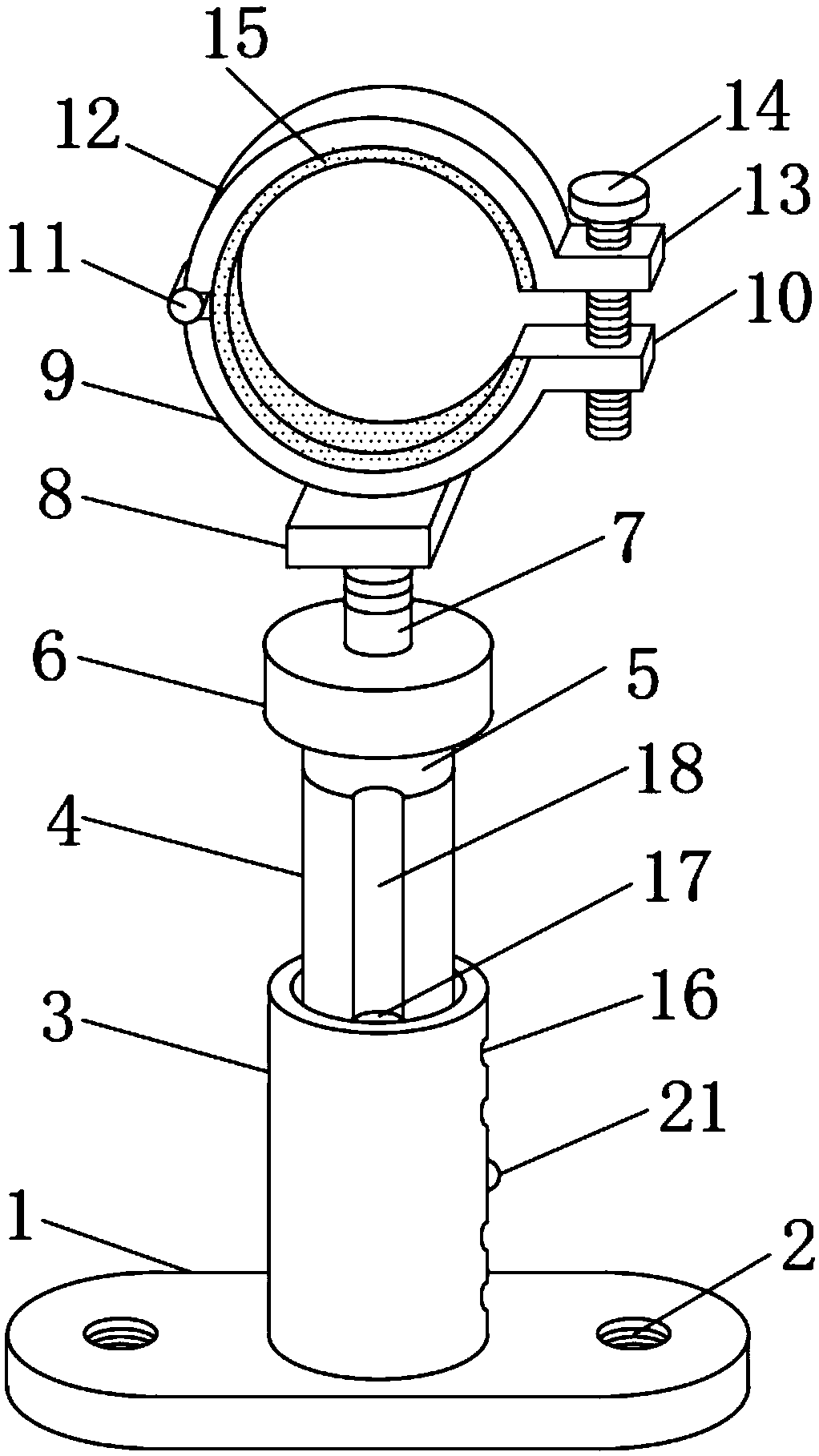
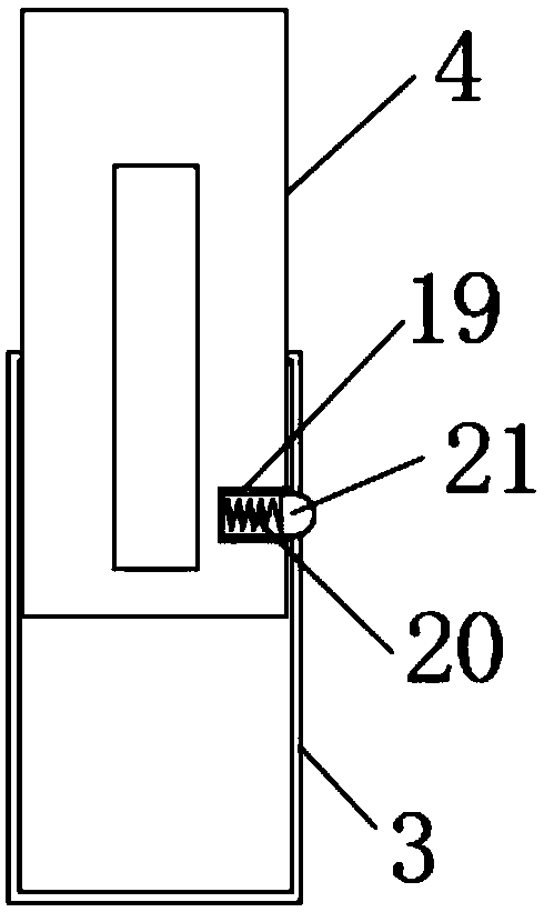
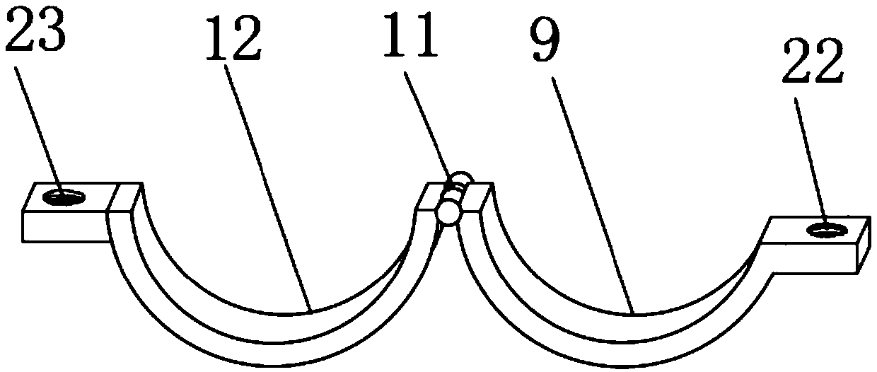
[0023] see Figure 1-6 , an optical fiber cable fixing device, comprising a base 1, fixing holes 2 are provided on both sides of the top of the base 1, a sleeve 3 is provided at the middle position of the top of the base 1, and a sleeve rod 4 is movably connected inside the sleeve 3 , the top of the sleeve rod 4 is provided with a fixed shaft 5, the top of the fixed shaft 5 is rotatably connected with a turntable 6, the top of the turntable 6 is provided with ...


PUM


Abstract

The invention discloses a fiber cable fixing device which comprises a base. Two sides of top of the base are provided with fixing holes. The middle position of top of the base is provided with a sleeve. The sleeve is internally connected with a sleeve rod. The top end of the sleeve rod is provided with a fixed shaft. The top of the fixed shaft is rotatably connected with a turntable. The top of the turntable is provided with a screw. According to the fiber cable fixing device, the sleeve and the sleeve rod are arranged; and a plurality of sets of through holes are arranged outside the sleeve;the bottom end of one side of the sleeve rod is provided with a recessed hole; the recessed hole is internally provided with a spring; one end of the spring is connected with a projection; the sleeverod performs upward or downward movement in the sleeve; the projection contacts with the inner wall of the sleeve; the spring is in a compressed state; when the projection corresponds with the throughhole, the spring is elongated, the projection outwards projects through the function of the spring and is snapped with the through hole. the projection can be snapped with different through holes according to an actual requirement, thereby adjusting the distance between the fiber cable and the wall or the ground.

Description

technical field [0001] The invention relates to the technical field of optical fiber cables, in particular to an optical fiber cable fixing device. Background technique [0002] With the rapid development of network technology, optical fiber has been widely used. The bare optical fiber is generally divided into three layers: the central high-refractive index glass core (core diameter is generally 50 or 62.5 μm), and the middle is a low-refractive index silica glass cladding. (The diameter is generally 125μm), the outermost is the resin coating for strengthening. Most optical fibers must be covered by several layers of protective structures before use. The coated cable is called an optical cable. The protective layer of the outer layer of the optical fiber and The insulating layer can prevent the damage of the surrounding environment to the optical fiber, such as water, fire, electric shock, etc. The optical cable is divided into: optical fiber, buffer layer and coating, the ...

Claims


Application Information

Patent Timeline
Patent Type & Authority Applications(China)
IPC IPC(8): G02B6/44H02G3/02
CPCH02G3/02G02B6/562
Inventor 陈友生
Owner 衡阳市光纤技术产学研管理有限公司
Why Eureka
Try Eureka