
A control method of high-precision numerical control lathe

A control method and technology of the turning side, which is applied in the direction of digital control, program control, electrical program control, etc., can solve the problems that the workpiece cannot be processed, the cutter head is large, and the turning side function cannot be realized, etc.

Active Publication Date: 2021-08-20
NANJING AGRICULTURAL UNIVERSITY
View PDF11 Cites 0 Cited by
  • Summary
  • Abstract
  • Description
  • Claims
  • Application Information

AI Technical Summary

Problems solved by technology

[0003] However, there are the following three problems in this kind of traditional lathe method: ① It is impossible to realize the machining of odd-numbered workpieces
Installing m cutters symmetrically on the cutter head can realize the processing of 2m square parts, but it cannot realize the processing of odd-numbered workpieces such as 1 square, 3 squares, etc.
② The radius of the cutter head is larger
Therefore, in order to ensure a certain machining accuracy, the cutter head of this type of machine tool is generally made relatively large, so that the turning function cannot be realized on a small machine tool.
Machining accuracy is not high
Therefore, this kind of processing method can only be used for some applications that do not require high precision.

Method used


Image

  • A control method of high-precision numerical control lathe
  • A control method of high-precision numerical control lathe
  • A control method of high-precision numerical control lathe

Examples


Embodiment Construction

[0039] The present invention will be further described below in conjunction with the accompanying drawings. The following examples are only used to illustrate the technical solution of the present invention more clearly, but not to limit the protection scope of the present invention.

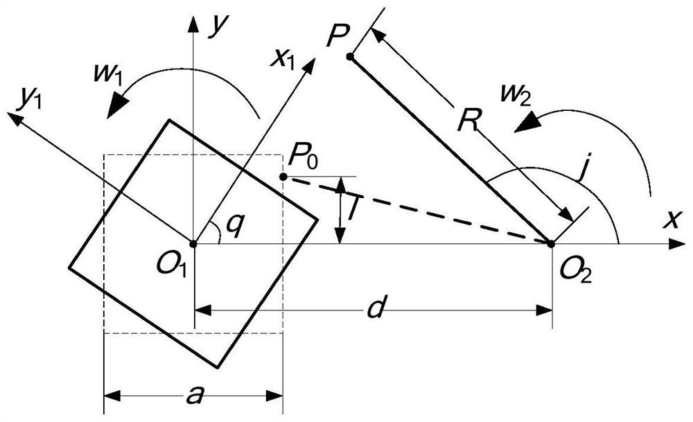
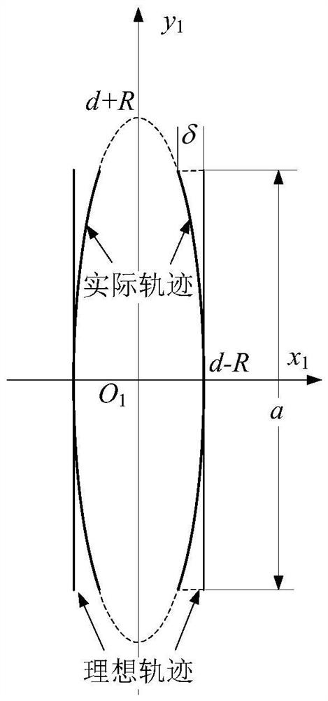
[0040] Such as figure 1 As shown, assuming that the workpiece is a regular n-gon, and the side length is a, when the car is square, the workpiece revolves around its center O 1 Rotate, the tool is fixed on the cutter head, and the cutter head revolves around the fixed point O 2 Rotate, the radius of gyration is R, the two turn to the same direction, and the rotation angles are θ, Two rotation centers O 1 o 2 The center-to-center distance is d. Fixed coordinate system xO 1 y (denoted as the coordinate system A) is fixed on the machine bed, and the motion coordinate system x 1 o 1 the y 1 (Denoted as coordinate system B) is fixedly connected to the workpiece and rotates with the rotation...


PUM


Abstract

The invention discloses a high-precision numerical control turning algorithm, which comprises the following steps: calculating the machining trajectory of a tool cutting point on a workpiece, setting the ideal machining trajectory of the workpiece, and calculating the interpolation coordinates on the ideal trajectory. The algorithm of the present invention only needs to ensure that the turning radius of the tool is greater than 1 / 7 of the side length of the car side, and there is basically no requirement for the size of the cutter head, so it can well meet the requirements of the car side of small-sized machine tools; the calculation of interpolation coordinates on the ideal trajectory , improving the machining accuracy.

Description

technical field [0001] The invention belongs to the technical field of numerical control machining, and in particular relates to a control method for a high-precision numerical control lathe. Background technique [0002] When processing the symmetrical facet on the rotary workpiece, the traditional milling process requires multiple clamping and indexing, and the production efficiency is not high. The turning machine tool uses the tool and the workpiece to rotate in the same direction at a constant speed ratio of 2:1 to realize approximate plane machining on the rotary workpiece, eliminating the need for secondary clamping and greatly improving the processing efficiency. [0003] However, there are the following three problems in this kind of traditional lathe method: ① It is impossible to realize the machining of odd-numbered workpieces. Since the tool and the workpiece rotate at a constant speed ratio of 2:1, when the workpiece rotates once, the tool rotates twice, so tha...

Claims


Application Information

Patent Timeline
Patent Type & Authority Patents(China)
IPC IPC(8): G05B19/19
CPCG05B19/19G05B2219/35349
Inventor 章永年王兴盛汪小旵卢伟康敏
Owner NANJING AGRICULTURAL UNIVERSITY
Learn More