Porous medium liquid-cooling cooling device, manufacturing method and use method thereof

A technology of porous media and manufacturing method, which is applied in cooling/ventilation/heating transformation, electrical components, electrical equipment structural parts, etc. Small convection heat transfer thermal resistance, improved heat dissipation effect, and the effect of enhancing heat dissipation capacity

Inactive Publication Date: 2019-03-29
SHANDONG CHAOYUE DATA CONTROL ELECTRONICS CO LTD
View PDF8 Cites 6 Cited by
  • Summary
  • Abstract
  • Description
  • Claims
  • Application Information

AI Technical Summary

Problems solved by technology

Overheating of components is one of the main reasons for the failure of electronic products, which seriously limits the improvement of the performance and reliability of electronic products, and also reduces the working life of equipment
Especially for components with high heat flux density (small size, high power consumption), heat dissipation is facing severe challenges. Studies have shown that: the temperature of semiconductor components increases by 10, and the reliability decreases by 50%. Therefore, the temperature rise of electronic equipment must be adjusted. control
[0005] Although air cooling is the simplest, lowest cost, and most mature heat dissipation method, due to the small heat capacity of the gas, air-cooled radiators that rely solely on heat conduction and convection, when the power of the device reaches 0.08W / cm2 or above, use air-cooled It is difficult to meet the heat dissipation requirements

Method used


Image

  • Porous medium liquid-cooling cooling device, manufacturing method and use method thereof
  • Porous medium liquid-cooling cooling device, manufacturing method and use method thereof
  • Porous medium liquid-cooling cooling device, manufacturing method and use method thereof

Examples


Embodiment Construction

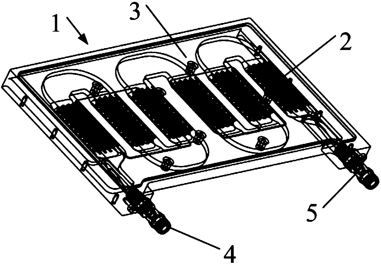
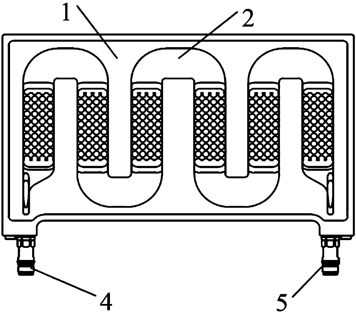
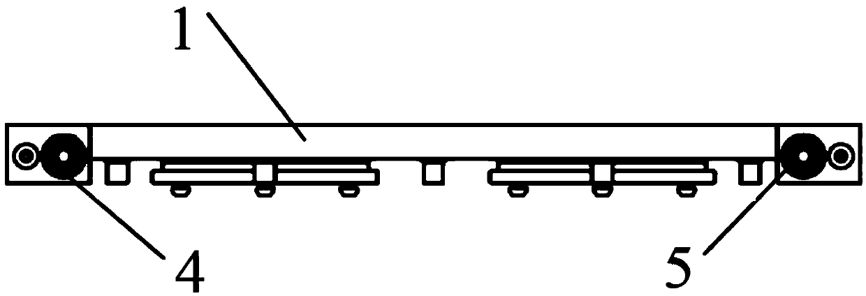
[0037] The invention provides a porous medium liquid cooling device, such as Figures 1 to 3 As shown, it includes: a base plate 1 , a porous medium module 2 and a cover plate 3 .

[0038] The substrate 1 is provided with a heat dissipation medium diversion groove, one end of the heat dissipation medium diversion groove is provided with a heat dissipation medium inlet joint 4, and the other end of the heat dissipation medium diversion groove is provided with a heat dissipation medium outlet joint 5; the porous medium module 2 It is filled into the heat dissipation medium diversion groove, so that the heat dissipation medium flows inside the heat dissipation medium diversion groove, causing disturbance; the cover plate 3 is covered on the base plate 1, and is sealed and connected with the base plate 1, so that the heat dissipation medium diversion groove forms a heat dissipation The medium guide chamber, the heat dissipation medium flows inside the heat dissipation medium guide...


PUM


Abstract

The invention provides a porous medium liquid-cooling cooling device, a manufacturing method and a use method thereof. A heat dissipating medium diversion groove is arranged on a substrate, and the heat dissipating medium diversion groove is provided with a heat dissipating medium inlet joint and a heat dissipating medium outlet joint. A porous medium module is filled in the heat dissipating medium diversion groove, so that a heat dissipating medium generates disturbance in a flowing manner in the heat dissipating medium diversion groove. A cover plate is covered on the substrate, and is sealingly connected with the substrate, so that the heat dissipating medium diversion groove forms a heat dissipating medium diversion cavity, and the heat dissipating medium flows in the heat dissipatingmedium diversion cavity. Thermal resistance of heat conduction is effectively reduced. A fluid flows through the internal of a porous medium, and heat convection is generated among the porous medium and a skeleton structure of the porous medium. The porous medium is large in specific surface area, and large in heat convection area. The skeleton structure is arranged in an intricate manner so thata fluid boundary layer on the surface of a skeleton is thinned or damaged, so as to reduce thermal resistance of heat convection. A porous medium liquid-cooling cooling plate can reduce thermal resistance during a heat transfer and enhance heat dissipation.

Description

technical field [0001] The invention relates to the field of heat dissipation of electronic devices, in particular to a porous medium liquid cooling device, a manufacturing method and a using method. Background technique [0002] At present, the current status of reinforced electronic equipment is as follows: ①The packaging density of electronic devices continues to increase, and its heat flux continues to increase; ②Electronic products continue to develop in the direction of miniaturization, with higher power and smaller dimensions. [0003] The volume of electronic components and their assembled electronic equipment is getting smaller and smaller, and the corresponding integration density is greatly increased. High heat flux electronic equipment has been formed and will reach a very high level with a faster development momentum. What follows is a sharp increase in the heat flux of electronic equipment, which poses new challenges for the thermal design of electronic equipme...

Claims


Application Information

Patent Timeline
Patent Type & Authority Applications(China)
IPC IPC(8): H05K7/20
CPCH05K7/20254H05K7/20272
Inventor 龚振兴国林钊王雪任洪伟
Owner SHANDONG CHAOYUE DATA CONTROL ELECTRONICS CO LTD
Why Eureka
Try Eureka