Supercharge Your Innovation With Domain-Expert AI Agents!

Bearing riveting system

A technology of bearings and feeding systems, which is applied in the manufacture of motor generators, electrical components, electromechanical devices, etc., can solve the problems of restricting the production efficiency of the production line, the inability to improve the production cycle, and long manual operation time, so as to reduce the labor intensity and improve The effect of fast production cycle and convenient operation

Pending Publication Date: 2019-04-02
长沙纽泰自动化科技有限公司
View PDF0 Cites 0 Cited by
  • Summary
  • Abstract
  • Description
  • Claims
  • Application Information

AI Technical Summary

Problems solved by technology

[0003] The existing technical scheme has a long manual operation time and cumbersome process content. It is easy to make people tired after working for a long time, and it cannot improve the production tempo, which restricts the production efficiency of the production line

Method used


Image

  • Bearing riveting system
  • Bearing riveting system
  • Bearing riveting system

Examples


Embodiment Construction

[0060]In order to make the purpose, technical solutions and advantages of the embodiments of the present invention clearer, the technical solutions in the embodiments of the present invention will be clearly and completely described below in conjunction with the drawings in the embodiments of the present invention. Obviously, the described embodiments It is a part of embodiments of the present invention, but not all embodiments. The components of the embodiments of the invention generally described and illustrated in the figures herein may be arranged and designed in a variety of different configurations.

[0061] Accordingly, the following detailed description of the embodiments of the invention provided in the accompanying drawings is not intended to limit the scope of the claimed invention, but merely represents selected embodiments of the invention. Based on the embodiments of the present invention, all other embodiments obtained by persons of ordinary skill in the art wit...


PUM


Abstract

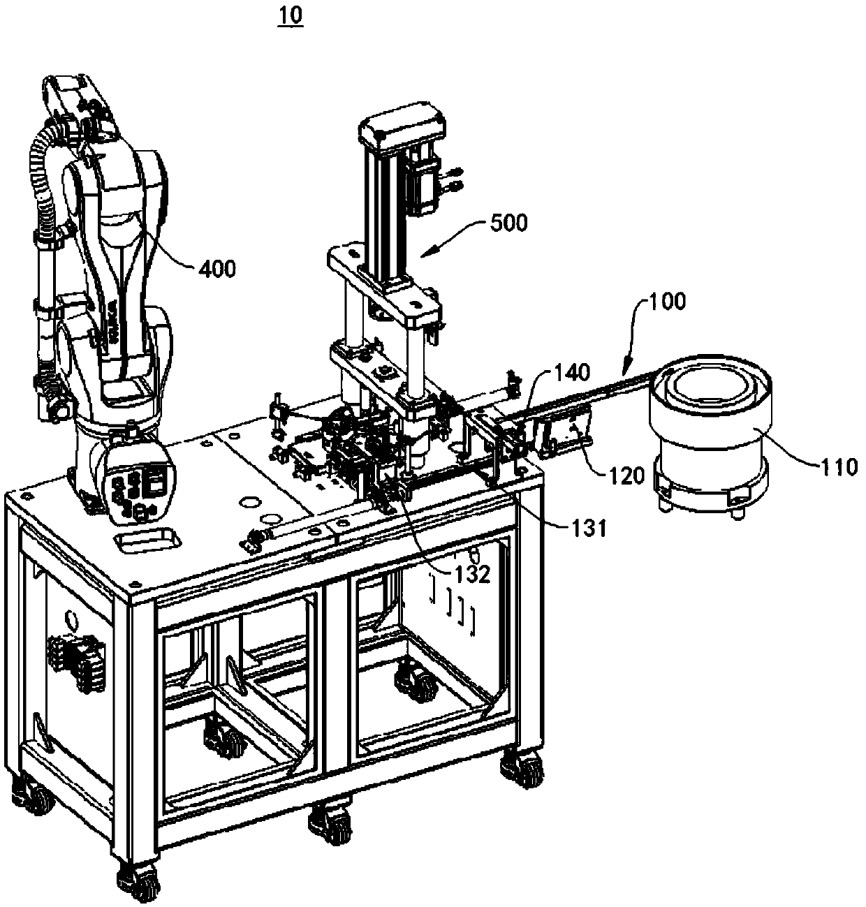
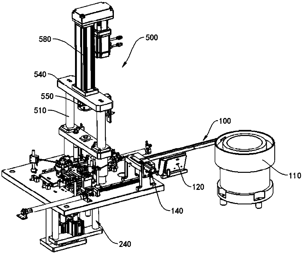
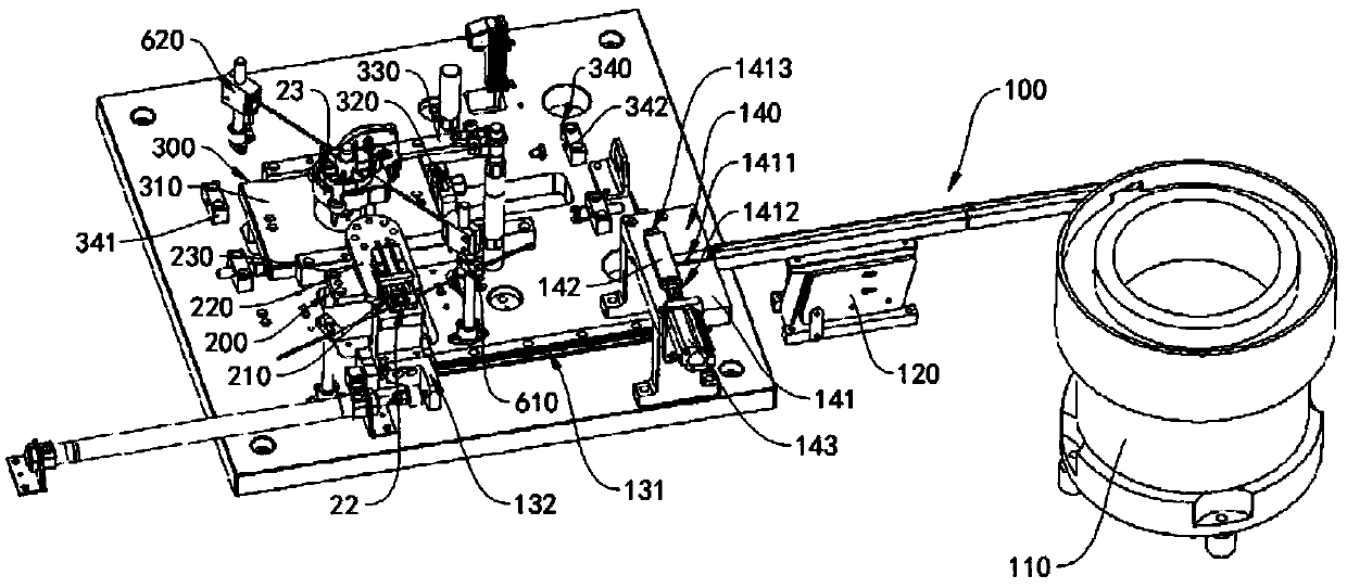
The invention relates to the field of automatic devices, in particular to a bearing riveting system. The bearing riveting system comprises a feeding system, a first material conveying system, a secondmaterial conveying system, an operation robot and a riveting system. The feeding system is configured to convey a first bearing to the first material conveying system. The first material conveying system comprises a material taking clamp, a joint plate and a rotating mechanism. The material taking clamp is arranged at the end portion of the joint plate, and the joint plate is arranged on the rotating mechanism. The second material conveying system comprises a material conveying sliding plate and a sliding plate driving device. The sliding plate driving device is connected with the material conveying sliding plate. After the material taking clamp of the first material conveying system places the first bearing to the preset position, away from a second bearing, of a motor shell, the slidingplate driving device drives the material conveying sliding plate to the riveting system. The sliding plate driving device drives the material conveying sliding plate to move a riveted shell to the position of an operation robot, the operation robot takes down the riveted shell, and the to-be-riveted second bearing and the to-be-riveted shell are sequentially arranged on the material conveying sliding plate.

Description

technical field [0001] The invention relates to the field of automation equipment, in particular to a bearing riveting system. Background technique [0002] The existing wiper motor pressure riveting oily bearing, the bearing is manually taken out and put into the pressure riveting fixture, the reducer casing is manually taken out and put into the pressure riveting fixture, and the press is started to complete the oily bearing pressing into the shell and riveting the anti-back riveting point of the bearing . [0003] The existing technical solution requires a long manual operation time, cumbersome process content, easy to make people tired after working for a long time, and cannot improve the production tempo, which restricts the production efficiency of the production line. Contents of the invention [0004] The object of the present invention includes providing a bearing riveting system, which can efficiently and quickly complete the bearing riveting work of the wiper m...

Claims


Application Information

Patent Timeline
IPC IPC(8): B25B27/06H02K15/14
CPCH02K15/14B25B27/06
Inventor 李国庆胡志明张虎马林华
Owner 长沙纽泰自动化科技有限公司
Features
  • R&D
  • Intellectual Property
  • Life Sciences
  • Materials
  • Tech Scout
  • Unparalleled Data Quality
  • Higher Quality Content
  • 60% Fewer Hallucinations
Learn More