
High temperature and high pressure jig dyeing device for cotton cloth production and processing

A high temperature and high pressure, cotton technology, applied in textile processing machine accessories, textile material processing, textile material processing equipment configuration, etc. problems, to achieve the effect of facilitating the jigging operation, facilitating the jigging effect, and improving the jigging effect

Inactive Publication Date: 2019-04-02
吴叶辉
View PDF13 Cites 1 Cited by
  • Summary
  • Abstract
  • Description
  • Claims
  • Application Information

AI Technical Summary

Problems solved by technology

[0006] In order to solve the above technical problems, the present invention provides a high-temperature and high-pressure dyeing device for cotton production and processing, to solve the problem that the existing similar dyeing devices have poor jigger effect on cotton cloth, and the cotton cloth jigger time is short and cannot be fully matched with dyes. Contact, it is easy to affect the color dyeing effect of cotton cloth; and the effect of stirring the dye inside the device is poor, and the concentration of dye is easy to be uneven when used, which affects the quality of cotton jig dyeing

Method used


Image

  • High temperature and high pressure jig dyeing device for cotton cloth production and processing
  • High temperature and high pressure jig dyeing device for cotton cloth production and processing
  • High temperature and high pressure jig dyeing device for cotton cloth production and processing

Examples


Embodiment

[0038] as attached figure 1 to attach Figure 13 Shown:

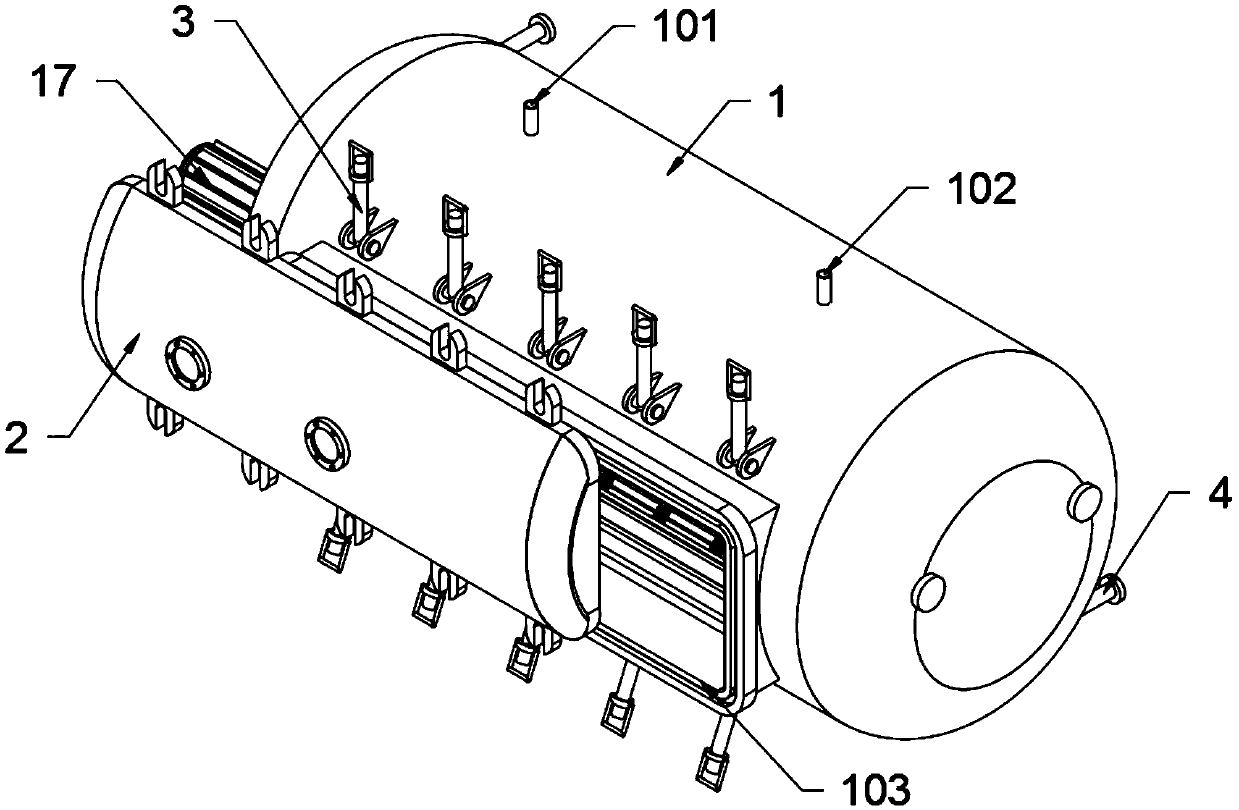
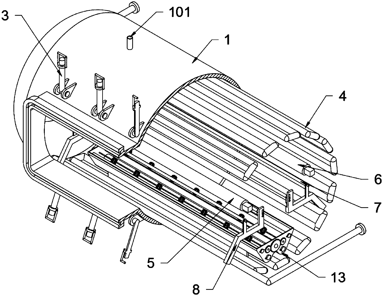
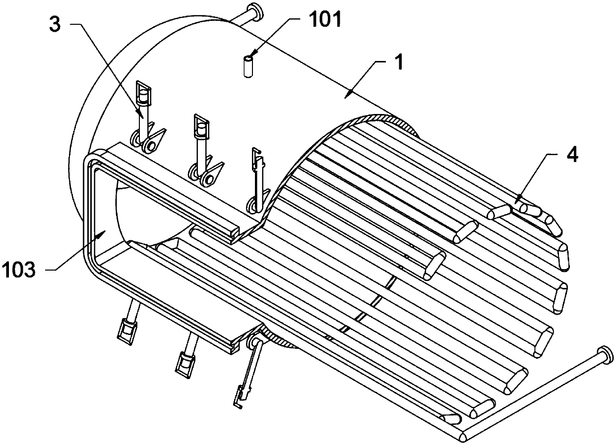
[0039]The invention provides a high-temperature and high-pressure dyeing device for cotton cloth production and processing, which includes a cavity 1, a pressure hole 101, a decompression hole 102, a material port 103, a sealing cover 2, a sealing bolt 3, a steam heating tube 4, and an active cloth rolling Roller 5, driven cloth rolling roller 6, reversing roller 7, support block 8, downhole 801, upper squeeze roller 9, lower squeeze roller 10, pull-down collar 11, tension spring 12, dye solution tank 13, dyeing Roller 14, transmission gear 15, stirring shaft 16, stirring blade 1601 and drive motor 17; The top of described cavity 1 is provided with a pressurizing hole 101 and a decompression hole 102 respectively, and pressurizing hole 101 passes high-pressure pipe and The external pressurized equipment is connected; the sealing cover 2 is fixed on the material port 103 at the front end of the cavity 1 through ten sea...


PUM


Abstract

The invention provides a high temperature and high pressure jig dyeing device for cotton cloth production and processing. The high temperature and high pressure jig dyeing device comprises a stirringblade and a driving motor; a pressurizing hole and a pressure-relief vent are respectively formed on the top of a chamber; the pressurizing hole is connected with an external pressurizing device through a high pressure pipeline; a sealing cover is fixed on the position of a port on the front end of the chamber through ten sealing bolts on the exterior of the chamber; the sealing bolts are in rotatable connection with the front end of the chamber; a steam heating pipe is located in the chamber; a driving cloth roller is in rotatable connection with the front end in the chamber. The high temperature and high pressure jig dyeing device is beneficial to guiding a to-be-dyed cotton cloth to pass by five dyeing rolls in dyestuff, prolonging running time of cotton cloth in dyestuff and promotingdyeing effect of cotton cloth. Due to the W-shaped distributed arrangement of five dyeing rolls, the cotton cloth can move up and down in a W form in the dyestuff, the exterior of the cotton cloth canbe in full contact with the dyestuff and the jig dyeing quality of cotton cloth can be promoted.

Description

technical field [0001] The invention belongs to the technical field of jigger dyeing of cotton cloth, and more specifically relates to a high-temperature and high-pressure jigger device for cotton cloth production and processing. Background technique [0002] Jig dyeing device is a relatively common equipment in textile equipment and an indispensable and important equipment in the process of textile dyeing. It is widely used in textile enterprises. [0003] The inventors found that there are existing similar dyeing jiggers, such as a new type of dyeing jigger mentioned in Patent Application No. The dyeing vat includes an inner vat and an outer vat, an inner vat is arranged in the outer vat, and a circulation heating mechanism is provided between the inner vat and the outer vat. The circulation heating mechanism includes a spiral tube and a heating box. 5 cloth rolling rollers, and the 5 cloth rolling rollers are arranged in a W shape, and the drying mechanism includes a tra...

Claims


Application Information

Patent Timeline
Patent Type & Authority Applications(China)
IPC IPC(8): D06B3/32D06B23/20D06B23/22D06B15/02D06B23/02D06B23/04D06B23/14
CPCD06B3/325D06B15/02D06B23/021D06B23/023D06B23/04D06B23/14D06B23/205D06B23/22
Inventor 吴叶辉孙亚杨静
Owner 吴叶辉
Learn More