LED lamp bead

A technology of LED lamp beads and accommodating cavity, which is applied in the direction of damage prevention measures of lighting devices, cooling/heating devices of lighting devices, lighting and heating equipment, etc., which can solve the problem of LED lamp bead color drift, small heat dissipation area, phosphor Precipitation and other issues

Inactive Publication Date: 2019-04-02
仪征市峰皓设备安装工程有限公司
View PDF0 Cites 0 Cited by
  • Summary
  • Abstract
  • Description
  • Claims
  • Application Information

AI Technical Summary

Problems solved by technology

Because the heat dissipation area of ​​the two pins 20 is too small, the temperature of the potting material resin colloid 50

Method used


Image

  • LED lamp bead
  • LED lamp bead
  • LED lamp bead

Examples


Embodiment Construction

[0014] In order to make the object, technical solution and advantages of the present invention clearer, the present invention will be further described below in conjunction with the accompanying drawings and specific embodiments. It should be understood that the specific embodiments described here are only used to explain the present invention, not to limit the present invention. Based on the embodiments of the present invention, all other embodiments obtained by persons of ordinary skill in the art without making creative efforts belong to the protection scope of the present invention.

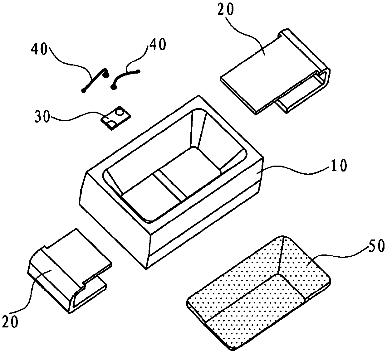
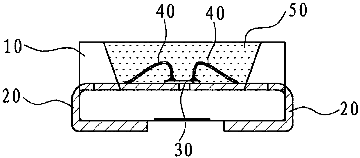
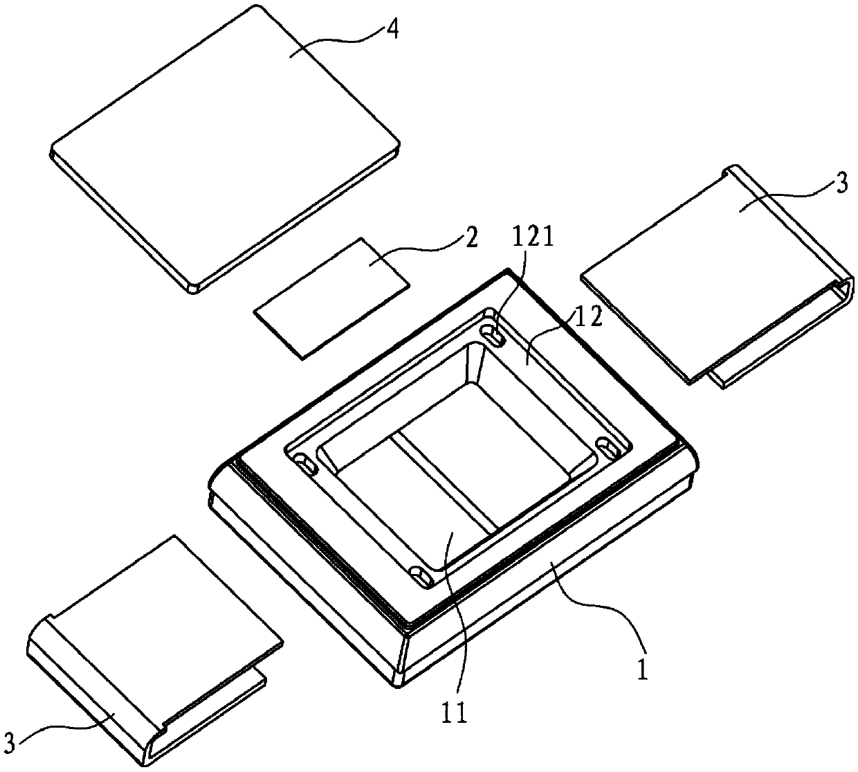
[0015] refer to Figure 3 to Figure 5 As shown, an LED lamp bead disclosed by the present invention includes a heat-conducting housing 1 provided with an accommodating cavity 11 , a flip chip 2 , two pins 3 and a fluorescent sheet 4 .

[0016] The two pins 3 are respectively embedded in the accommodating chamber 11 of the heat-conducting shell 1, and the bottom of the accommodating chamber 1...


PUM


Abstract

The invention relates to an LED lamp bead. The LED lamp bead comprises a heat conduction shell with an accommodating cavity, a flip chip, a fluorescence plate and two tube pins, wherein the two tube pins are embedded in the accommodating cavity of the heat conduction shell; the flip chip attaches to the two tube pins, are electrically connected with the two tube pins, and are positioned in the accommodating cavity; and the fluorescence plate is fixed on the heat conduction shell. For the LED lamp bead, the heat conduction shell and fluorescence plate technologies are adopted, a resin glue bodydoes not need to be poured in the accommodating cavity, thus the integral thickness of the LED lamp bead is enabled to be small, then the heat dissipation effect is good, and the color shift is avoided; and the flip chip does not need wire bonding and dispensing of crystal fixing glue, so that the thickness of the LED lamp bead is enabled to be small.

Description

technical field [0001] The invention relates to an LED lamp bead. Background technique [0002] Such as figure 1 and figure 2 As shown, an LED lamp bead disclosed in the prior art includes a housing 10 with a housing cavity, two pins 20 , a chip 30 and two gold wires 40 ; the two pins 20 are symmetrically embedded in the housing cavity 10 , respectively located on both sides of the shell 10, one pin 20 as the positive pole, and the other side pin 20 as the negative pole; the chip is installed on the two pins 20 and is located in the accommodating cavity, and the chip 30 is connected to the positive tube through the gold wire 40 respectively. Pin 20 and negative pin 20 are connected. [0003] Since the housing 10 is an ordinary housing without heat conduction properties, its heat dissipation is mainly conducted by the two pins 20. In order to make the LED lamp bead emit white light, the resin colloid 50 with heat conduction properties is usually filled in the accommodatin...

Claims


Application Information

Patent Timeline
IPC IPC(8): F21K9/20F21V9/20F21V15/01F21V17/10F21V17/16F21V19/00F21V23/06F21V29/507F21V31/00F21Y115/10
CPCF21K9/20F21V9/20F21V15/01F21V17/101F21V17/164F21V19/002F21V19/005F21V23/06F21V29/507F21V31/00F21Y2115/10
Inventor 陆远林
Owner 仪征市峰皓设备安装工程有限公司
Why Eureka
Try Eureka