
Optical fiber grating acceleration sensor based on diaphragm type equal-strength cantilever beam structure

An acceleration sensor, fiber grating technology, applied in the direction of using inertial force for acceleration measurement, instruments, measuring devices, etc., can solve the problems of the ordinary cantilever beam structure's weak lateral anti-interference ability, etc., to solve the problem of weak lateral anti-interference ability, The effect of simple processing and installation and large measuring range

Inactive Publication Date: 2019-04-02
NORTHWEST UNIV +1
View PDF11 Cites 6 Cited by
  • Summary
  • Abstract
  • Description
  • Claims
  • Application Information

AI Technical Summary

Problems solved by technology

Although the invention improves the sensitivity, it still has the disadvantage that the transverse anti-interference ability of the ordinary cantilever beam structure is not strong

Method used


Image

  • Optical fiber grating acceleration sensor based on diaphragm type equal-strength cantilever beam structure
  • Optical fiber grating acceleration sensor based on diaphragm type equal-strength cantilever beam structure
  • Optical fiber grating acceleration sensor based on diaphragm type equal-strength cantilever beam structure

Examples


Embodiment 1

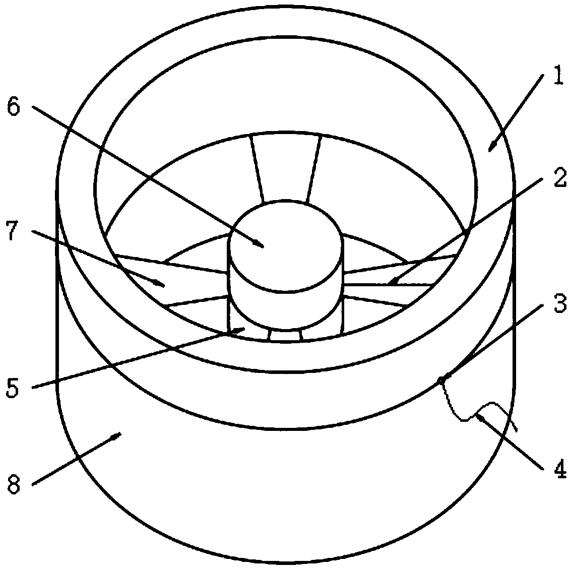
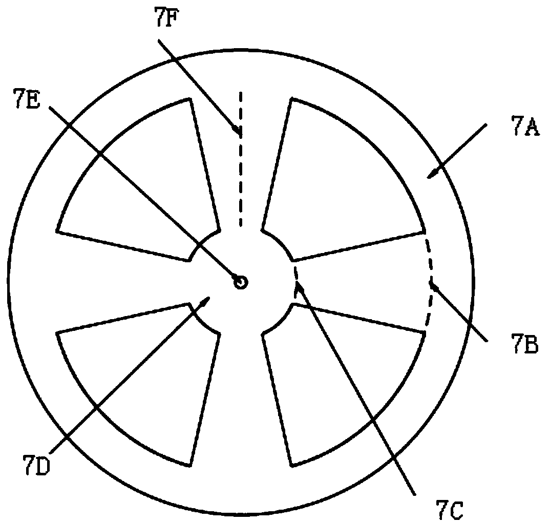
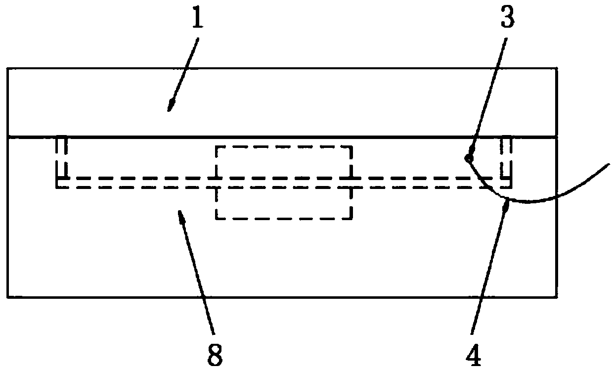
[0023] see Figure 1-3 , the present invention provides a technical solution: a fiber grating acceleration sensor based on a diaphragm-type equal-strength cantilever beam structure, including a housing 8 and a diaphragm 7, a lower mass 5, an upper mass 6 and The sensing grating 2, the lower mass 5 and the upper mass 6 are located at the geometric center of the diaphragm 7 and are fixed at the center of the diaphragm 7. The diaphragm 7 is fixed to the shell through the hollow upper cover 1 provided at the upper end of the shell 8. The inner wall of the body 8; the inside of the diaphragm 7 is cut into symmetrical four-equal-strength cantilever beams, and a sensing grating 2 is arranged on the upper surface of one of the cantilever beams, and the optical fiber pigtail 4 on the sensing grating 2 communicates with the external solution through the optical fiber exit hole 3 connected to the tuning unit.

[0024] In this embodiment, a concave platform is provided in the casing 8, a...

Embodiment 2

[0027] In this embodiment, the shell 8 and the hollow upper cover 1 are made of stainless steel, the lower mass 5 and the upper mass 6 are made of plexiglass, and the upper and lower masses are cylindrical structures with a diameter of 10mm and a height of 2.5mm, the total mass of the upper and lower mass blocks is 0.5g, the diaphragm 7 is made of beryllium bronze material, the thickness is 0.5mm, the outer diameter is 50mm, the width of the diaphragm outer ring 7A is 5mm, the diameter of the diaphragm inner ring 7D is 10mm, the diaphragm The small hole 7E in the center of the film has a diameter of 1.5mm, the length of the outer side 7B of the diaphragm cantilever beam (at the dotted line) is 6mm, the length of the inner side 7C of the diaphragm cantilever beam (at the dotted line) is 2mm, and the wavelength of the sensor grating 2 is 1550nm. The length of the grid area of ​​the grating 2 is 5 mm, and the other components and the connection relationship of the components are t...


PUM

PropertyMeasurementUnit
Thicknessaaaaaaaaaa
Thicknessaaaaaaaaaa
Diameteraaaaaaaaaa

Abstract

The invention belongs to the technical field of an optical fiber sensor, and in particular relates to an optical fiber grating acceleration sensor based on a diaphragm type equal-strength cantilever beam structure. The acceleration sensor comprises a diaphragm and an inertial mass block which are disposed in a shell, and a sensing grating, wherein the inertial mass block is located in a geometriccenter of the diaphragm and is fixed below the diaphragm; the diaphragm is fixed on an inner wall of the shell; an interior of the diaphragm is cut into four symmetrical equal-strength cantilever beams; the sensing grating is disposed on an upper surface of one of the cantilever beams; and a tail fiber at one end of the sensing grating is connected with an external demodulation unit after passingthrough an optical fiber outlet. The sensor combines the advantages of the cantilever beam and the circular diaphragm to fundamentally solve the defects of poor lateral anti-interference capability ofthe traditional cantilever beam and low acceleration response sensitivity of the ordinary circular diaphragm; and the sensor has the advantages of reasonable design, simple structure, large measuringrange, simple processing and installation and high sensitivity and can be used for seismic exploration of oil and gas resources.

Description

technical field [0001] The invention belongs to the technical field of optical fiber grating sensing, and in particular relates to an optical fiber grating acceleration sensor based on a membrane-type equal-strength cantilever beam structure. Background technique [0002] In the process of seismic exploration, the seismic source is used to excite seismic waves by artificial methods. After the seismic waves propagate through the stratum rock medium, the reflected or transmitted signals must be received by a special instrument. This special instrument for receiving seismic waves is seismology. With the rapid development of seismic exploration technology in wells, the requirements for various performance parameters of geophones are also increased. At present, traditional electromagnetic geophones are generally used in seismic exploration. Relatively speaking, its series Less, low detection sensitivity, low precision, narrow frequency range, susceptible to electromagnetic interf...

Claims


Application Information

Patent Timeline
IPC IPC(8): G01H9/00G01P15/03
CPCG01H9/004G01P15/03
Inventor 乔学光樊伟冯德全白燕禹大宽高宏王向宇
Owner NORTHWEST UNIV
Learn More