
Flexible multi-state adjustment switch adjustment-based voltage adjustment system

A technology of voltage regulation and regulation switch, applied in the direction of AC network voltage regulation, etc., can solve the problems of development lag, simple lack of primary equipment, lack of innovation and progress, etc., to promote equalization, precise power exchange control and power flow optimization capabilities, The effect of increasing the power continuously controllable state

Inactive Publication Date: 2019-04-02
DATONG POWER SUPPLY COMPANY OF STATE GRID SHANXI ELECTRIC POWER
View PDF5 Cites 3 Cited by
  • Summary
  • Abstract
  • Description
  • Claims
  • Application Information

AI Technical Summary

Problems solved by technology

In recent years, the development of primary equipment technology for smart distribution networks has mostly focused on the "source" and "load" levels. At the distribution "network" level, the primary equipment that can support flexible dispatching and control of the power grid is still relatively simple and scarce, and its development is relatively lagging behind. , compared with traditional power distribution equipment, it lacks essential innovation and progress
[0004] In the existing technology, the distribution network is facing huge challenges such as customization and diversification of power demand, large-scale distributed power access, and complex power flow coordination and control.
These problems are difficult to be effectively solved at the same time by using traditional control methods such as conventional switches to regulate the voltage of the distribution network.

Method used


Image

  • Flexible multi-state adjustment switch adjustment-based voltage adjustment system
  • Flexible multi-state adjustment switch adjustment-based voltage adjustment system

Examples


Embodiment Construction

[0017] In order to be able to understand the above objectives, features and advantages of the application more clearly, the application will be further described in detail below with reference to the accompanying drawings and specific implementations. It should be noted that the embodiments of the application and the features in the embodiments can be combined with each other if there is no conflict.

[0018] In the following description, many specific details are explained in order to fully understand this application. However, this application can also be implemented in other ways different from those described here. Therefore, the scope of protection of this application is not disclosed below. Limitations of specific embodiments.

[0019] The following combination figure 1 with figure 2 The embodiments of this application are described.

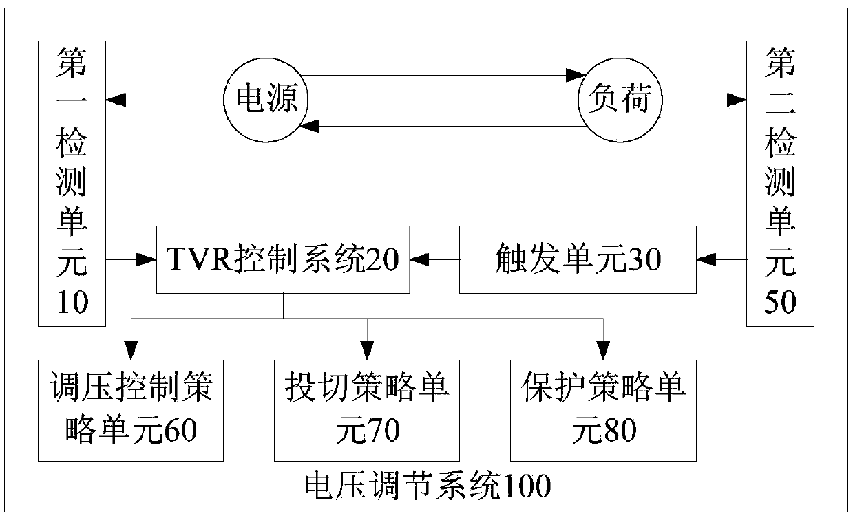
[0020] Such as figure 1 As shown, this embodiment provides a voltage regulation system based on flexible multi-state regulation switch regula...


PUM


Abstract

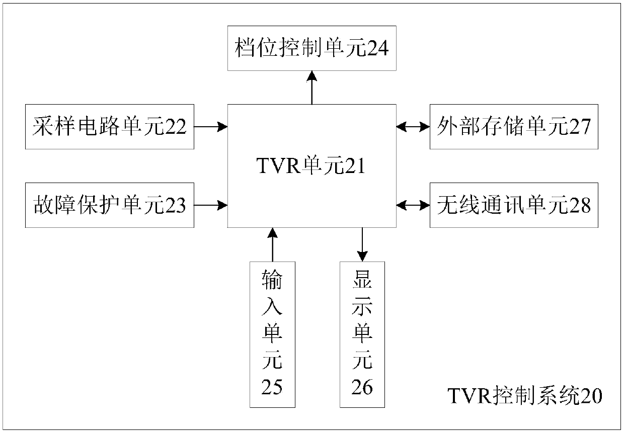
The invention discloses a flexible multi-state adjustment switch adjustment-based voltage adjustment system. The system is characterized in that a detection unit comprises a first detection unit and asecond detection unit, wherein the first detection unit is connected between a power supply in a power distribution network and a first detection end of a TVR control system, the second detection unit is connected between a load in the power distribution network and a trigger unit and is used for detecting a power supply current signal, a power supply voltage signal, a load voltage signal and a load current signal in the power distribution network, the trigger unit is connected to a second detection end of the TVR control system and is used for sending an external fault signal to the TVR control system, a first output end of the TVR control system is connected to a voltage regulation control strategy unit, the TVR control system is used for generating and sending a voltage regulation control signal, and the voltage regulation control strategy unit is used for adjusting an output voltage of the power supply according to the voltage regulation control signal. With the system disclosed by the technical scheme, the running condition of the power distribution network is monitored and adjusted in real time, and the voltage adjustment accuracy is improved.

Description

Technical field [0001] This application relates to the technical field of power distribution network transformation, and specifically to a voltage regulation system based on flexible multi-state regulation switch regulation. Background technique [0002] With the increase in the penetration rate of distributed power generation, the original structure of the distribution network restricts power transmission and distribution. However, the re-planning of the grid and the re-construction of distribution lines in the urban distribution network face problems such as the scarcity of transmission corridors and the high construction cost. Therefore, it is necessary to make full use of the power distribution capacity of the existing grid topology. On the other hand, the intermittency and volatility of distributed power generation will cause rapid changes in the power flow of the distribution network, which may cause the power distribution equipment to exceed the limit during operation unde...

Claims


Application Information

Patent Timeline
Patent Type & Authority Applications(China)
IPC IPC(8): H02J3/12
CPCH02J3/12
Inventor 赵锐赵飞尚文薛辉郭鑫闫文超牛志鹏冯有福
Owner DATONG POWER SUPPLY COMPANY OF STATE GRID SHANXI ELECTRIC POWER
Learn More