
Micro-motor end cover assembly automatic brush inserting machine

A technology of micro-motor and brush-insertion machine, which is applied to electric components, manufacturing motor-generators, electrical components, etc., can solve the problems affecting the assembly quality and efficiency of the end cover assembly, reduce manual loading and unloading and the process of inserting brushes, and improve the Insertion efficiency, the effect of improving assembly quality and efficiency

Active Publication Date: 2019-04-02
深圳市鑫合利电子有限公司
View PDF2 Cites 6 Cited by
  • Summary
  • Abstract
  • Description
  • Claims
  • Application Information

AI Technical Summary

Problems solved by technology

[0003] The micro motor is composed of main parts such as end cover, stator and machine hub, among which the end cover includes end cover, bearing and brush. Take the bearing and place it in the corresponding groove in the end cover, then manually remove the end cover and transfer it to the workbench of the brush, then manually divide the strip brush into individual brushes and bend them, Two brushes are sequentially installed in the corresponding grooves of the cover to form the end cover assembly, but because the instability of manual participation directly affects the assembly quality and efficiency of the end cover assembly, therefore, there are defects in the prior art and need to be improved

Method used


Image

  • Micro-motor end cover assembly automatic brush inserting machine
  • Micro-motor end cover assembly automatic brush inserting machine
  • Micro-motor end cover assembly automatic brush inserting machine

Examples


Embodiment Construction

[0025] In order to facilitate the understanding of the present invention, the present invention will be described in more detail below in conjunction with the accompanying drawings and specific embodiments. Preferred embodiments of the invention are shown in the accompanying drawings. However, the present invention can be implemented in many different forms and is not limited to the embodiments described in this specification. Rather, these embodiments are provided for the purpose of making the disclosure of the present invention more thorough and comprehensive.

[0026] It should be noted that when an element is referred to as being “fixed” to another element, it can be directly on the other element or there can also be an intervening element. When an element is referred to as being "connected to" another element, it can be directly connected to the other element or intervening elements may also be present. The terms "fixed", "integrated", "left", "right" and similar expres...


PUM


Abstract

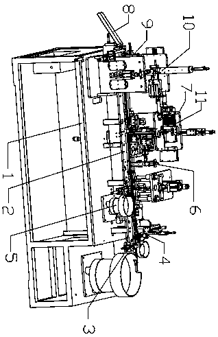
The invention relates to a micro-motor end cover assembly automatic brush inserting machine, comprising a workbench, wherein a support frame is arranged on the upper part of the workbench; a transfertrack is arranged in the middle part of the support frame; a plurality of carrying seats for carrying end covers are arranged at equal intervals on the upper part of the transfer track; a transfer power portion for driving the plurality of carrying seats to move horizontally leftwards is located at the lower part of the transfer track; an end cover loading mechanism, an iron sheet loading mechanism, a bearing loading mechanism, a gluing mechanism, a first brush inserting mechanism, a second brush inserting mechanism, a brush pressing mechanism and a unloading tank are successively disposed onthe workbench from the right to the left at the side of the transfer track in the conveying direction of the end covers. The parts of an end cover assembly, such as the end cover, the iron sheet, thebearing and the brush are successively installed in the corresponding grooves in the end cover by the cooperation of multiple mechanisms on the workbench, thereby reducing the manual loading and unloading process and the brush insertion process, and improving the assembly quality and efficiency of the end cover assembly, and achieving a good market application value.

Description

technical field [0001] The invention relates to the field of motor assembly technology, in particular to an automatic brush insertion machine for micro-motor motor end cover assembly. Background technique [0002] Micro motor is a motor with small volume and capacity, and its output power is generally below several hundred watts. It is a motor with special requirements for use, performance and environmental conditions. The full name is micro special motor, referred to as micro motor; brush is an important component of the motor It is responsible for conducting current between the rotating part and the stationary part. Because it is mostly made of graphite, it is also called carbon brush. In actual use, a slip ring is usually equipped with at least two brushes to avoid deformation due to poor contact of a single brush. into a broken circuit. [0003] The micro motor is composed of main parts such as end cover, stator and machine hub, among which the end cover includes end co...

Claims


Application Information

Patent Timeline
IPC IPC(8): H02K15/00
CPCH02K15/00
Inventor 许素芝
Owner 深圳市鑫合利电子有限公司
Learn More