Piston ring clamping tool

A technology for piston rings and tools, which is applied in the field of piston ring clamping tools to achieve the effects of increasing service life, avoiding scratches, and improving assembly quality and efficiency

Active Publication Date: 2017-09-29
ANHUI JIANGHUAI AUTOMOBILE GRP CORP LTD
View PDF5 Cites 0 Cited by
  • Summary
  • Abstract
  • Description
  • Claims
  • Application Information

AI Technical Summary

Problems solved by technology

[0004] The purpose of the present invention is to provide a piston ring clamping tool to provide a limit when clamping

Method used


Image

  • Piston ring clamping tool
  • Piston ring clamping tool
  • Piston ring clamping tool

Examples


Example Embodiment

[0048] The following describes in detail the embodiments of the present invention, examples of which are illustrated in the accompanying drawings, wherein the same or similar reference numerals refer to the same or similar elements or elements having the same or similar functions throughout. The embodiments described below with reference to the accompanying drawings are exemplary and are only used to explain the present invention, but not to be construed as a limitation of the present invention.

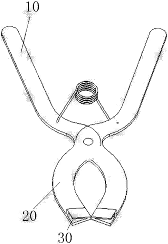
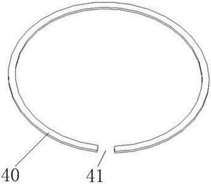
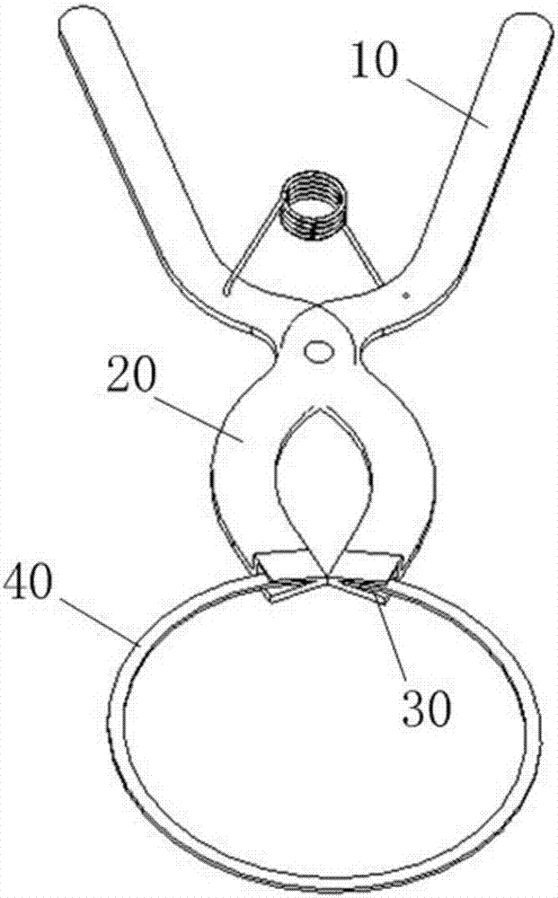
[0049] Please also refer to Figure 4 to Figure 8 , the embodiment of the present invention provides a piston ring clamping tool, which includes a handle 100 and a clamp 200, the handle 100 controls the opening and closing of the clamp 200, and the end of the clamp 200 is provided with a clamp for clamping the piston ring 400 The clamping slot 210 of the piston ring, wherein the piston ring clamping tool further includes a limit control mechanism 300, and the limit control mechanism ...


PUM


Abstract

The embodiment of the invention provides a piston ring clamping tool. The piston ring clamping tool comprises a limiting control mechanism. The limiting control mechanism comprises a shell, a motor and an inductor. The shell is fixedly arranged on the clamp, and the shell and a clamping groove are formed in the two sides of the clamp correspondingly. The shell is provided with a sliding hole, the sliding hole protrudes out of the end portion of the clamp, and a baffle is arranged in the sliding hole in a sliding manner. The motor is fixedly arranged on the shell, and the motor controls the baffle to slide in the sliding hole. The inductor is fixedly arranged in the shell and electrically connected with the motor. According to the piston ring clamping tool provided in the embodiment, a piston ring is prevented from sliding out of the clamping groove due to elastic deformation of the piston ring in the expanding process through stretching and contracting of the baffle, and piston scratching is avoided; and meanwhile, through cooperation of the motor, a cam shaft, a rocker arm and a rocker arm support, automatic control over piston ring limiting is achieved, the piston ring assembling quality and efficiency are effectively improved, and meanwhile the service life of the tool is prolonged.

Description

technical field [0001] The invention relates to a piston ring assembly mechanism, in particular to a piston ring clamping tool. Background technique [0002] In the traditional piston ring assembly, in the non-production line assembly environment, piston ring clamping tooling is often used. figure 1 It is a structural schematic diagram of the piston ring clamping tooling in the prior art, figure 2 Schematic diagram of the structure of the piston ring, image 3 The state diagram of tensioning the piston ring for the piston ring clamping tool, and refer to Figure 1 to Figure 3 , the piston ring clamping tool includes a handle 10 and a clamp 20, the end of the clamp 20 is provided with a slot 30, the piston ring 40 is provided with an opening 41, and the two ends of the opening 41 can be clamped in the slot ,Such as image 3 shown. During the assembly process, the handle 10 is held tightly by manpower to open the piston ring 40, and the diameter of the piston ring 40 is ...

Claims


Application Information

Patent Timeline
IPC IPC(8): B25B27/14B25B7/00
CPCB25B7/00B25B27/14
Inventor 刘海报张来文詹坤陶晓龙闫敏李浩刘飞张宝平
Owner ANHUI JIANGHUAI AUTOMOBILE GRP CORP LTD
Why Eureka
Try Eureka