
Lining for composite container pressure accumulator, composite container pressure accumulator, and manufacturing method of lining for composite container pressure accumulator

A composite container and pressure accumulator technology, applied to the outer wall of the container structure, manufacturing tools, pressure vessels, etc., can solve the problems of high cost of raw materials, thick storage container wall, increased container weight, etc.

Active Publication Date: 2020-10-27
JFE STEEL CORP
View PDF9 Cites 0 Cited by
  • Summary
  • Abstract
  • Description
  • Claims
  • Application Information

AI Technical Summary

Problems solved by technology

[0006] However, stainless steel such as SUS316 has low strength, so when the hydrogen pressure is increased to 70 MPa, for example, the wall thickness of the storage container becomes extremely thick, which increases the weight of the container
Therefore, the size of the storage container is limited, the amount of hydrogen stored in the container is reduced, not only that, but there is also a problem of high raw material cost and poor economy

Method used


Image

  • Lining for composite container pressure accumulator, composite container pressure accumulator, and manufacturing method of lining for composite container pressure accumulator
  • Lining for composite container pressure accumulator, composite container pressure accumulator, and manufacturing method of lining for composite container pressure accumulator
  • Lining for composite container pressure accumulator, composite container pressure accumulator, and manufacturing method of lining for composite container pressure accumulator

Examples


Embodiment

[0144] Next, the present invention will be described more specifically based on examples. The following examples show preferred examples of the present invention, and the present invention is not limited by these examples.

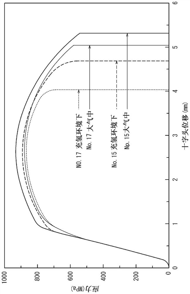
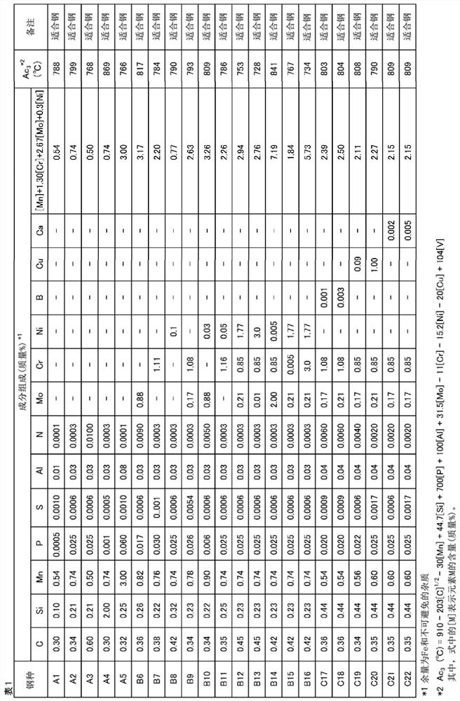
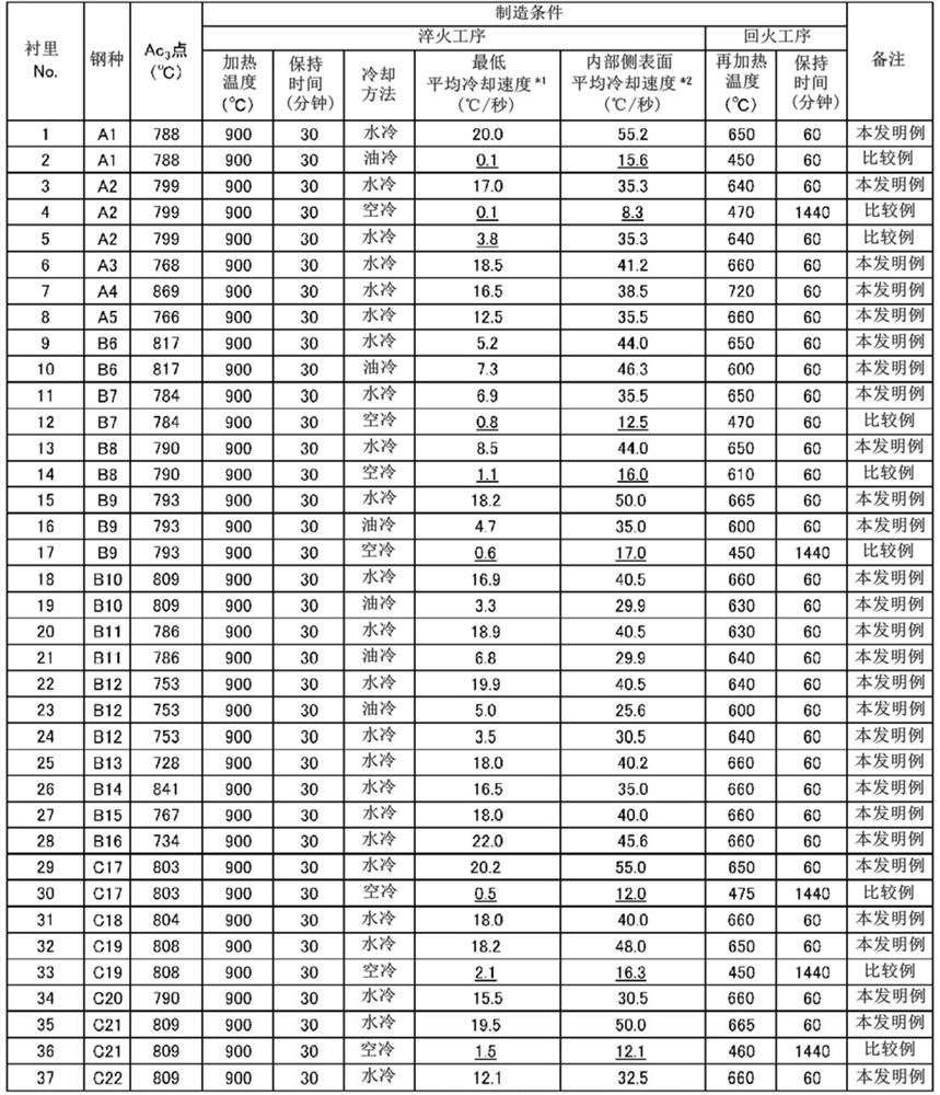
[0145] Liners for composite tank pressure accumulators made of steel materials with the composition shown in Table 1 were manufactured. The fabrication steps are described below. First, a billet having the composition shown in Table 1 was produced, and the billet was rolled and expanded with heat to obtain a seamless steel pipe. The production of the above-mentioned steel pipe is carried out under the conditions that pipe expansion is completed at 820° C. or higher. The obtained steel pipe was air-cooled, formed into a liner shape, and further quenched and tempered. Table 2 shows the quenching and tempering conditions. The minimum cooling rate in the quenching process shown in Table 2 was measured by installing a thermocouple on the inner side surface ...


PUM

PropertyMeasurementUnit
thicknessaaaaaaaaaa
tensile strengthaaaaaaaaaa
strengthaaaaaaaaaa

Abstract

The present invention provides a liner for a composite container pressure accumulator with a tensile strength of 850 MPa or more, which is suitable for a composite container pressure accumulator storing high-pressure hydrogen, and has a structure with little material deterioration in a hydrogen environment. A liner for a composite container pressure accumulator, which has a predetermined composition, and has an area percentage of martensite at the 1 / 4 position of the wall thickness on the inner side of 30% or more, and the area percentage of martensite at the 1 / 4 position of the wall thickness on the inner side The total area percentage of martensite and bainite is 95% or more, and the total area percentage of martensite and bainite is 95% or more in the center of the wall thickness. The wall thickness of the wall is more than 20mm, and the tensile strength of the central part of the wall thickness is more than 850MPa.

Description

technical field [0001] The present invention relates to a liner for a composite vessel pressure accumulator, in particular to a liner for a composite vessel pressure accumulator suitable for storing high-pressure hydrogen. In addition, the present invention relates to a composite container accumulator in which the above-mentioned liner for the composite container pressure accumulator is coated with a carbon fiber reinforced resin, and a method for manufacturing the above-mentioned liner for the composite container pressure accumulator. Background technique [0002] Fuel cell vehicles using hydrogen as fuel do not emit carbon dioxide (CO 2 ), the energy efficiency is also excellent, therefore, as a solution to CO 2 Cars with emission issues and energy issues are highly anticipated. In order to popularize such fuel cell vehicles, in hydrogen refueling stations for supplying hydrogen to fuel cell vehicles, a container (storage station) with excellent strength and durability c...

Claims


Application Information

Patent Timeline
Patent Type & Authority Patents(China)
IPC IPC(8): C22C38/00C21D9/08C22C38/06C22C38/58F16J12/00F17C1/02
CPCC21D9/08C22C38/00C22C38/06C22C38/58F16J12/00C21D8/10F17C1/02C21D2211/002C21D2211/008C22C38/02C22C38/04C22C38/22Y02E60/32F17C2203/011F17C2203/0604F17C2203/0607F17C2203/0639
Inventor 冈野拓史高木周作
Owner JFE STEEL CORP
Learn More