compressor

A compressor and compression mechanism technology, applied in the field of compressors, can solve the problems of reduced sealing of the compression mechanism, increased leakage loss, insufficient oil supply, etc., to achieve the effect of suppressing leakage loss and sufficient oil supply

Active Publication Date: 2019-12-31
MITSUBISHI ELECTRIC CORP
View PDF2 Cites 0 Cited by
  • Summary
  • Abstract
  • Description
  • Claims
  • Application Information

AI Technical Summary

Problems solved by technology

In this compressor, when the rotational speed becomes too low, the amount of oil supplied from the bottom via the oil supply path is insufficient, and the sealing performance of the compression mechanism part may decrease, resulting in an increase in leakage loss.

Method used


Image

  • compressor
  • compressor
  • compressor

Examples


Embodiment approach 1

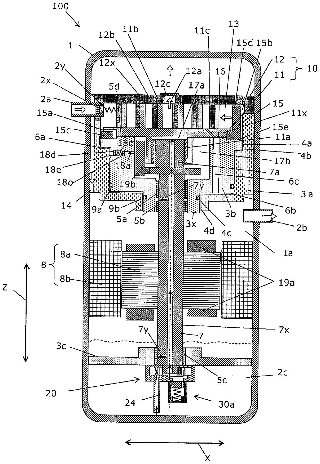
[0033] figure 1 It is a schematic longitudinal sectional view showing the compressor according to Embodiment 1 of the present invention. Below, refer to figure 1 The configuration of the compressor 100 will be described. figure 1 The compressor 100 is a so-called vertical scroll compressor, and compresses and discharges a working gas such as refrigerant, for example. The compressor 100 includes an airtight container 1, a compression mechanism unit 10, a motor 8, a drive shaft 7, an oil storage space 2c, an oil supply pump 20, and a differential pressure oil supply mechanism 30a.

[0034] The airtight container 1 is formed in a cylindrical shape, for example, and has pressure resistance. A suction pipe 2 a for taking working gas into the airtight container 1 is connected to one side of the airtight container 1 , and a discharge pipe 2 b for discharging compressed working gas from the airtight container 1 to the outside is connected to the other side. Arrows in the piping sh...

Embodiment approach 2

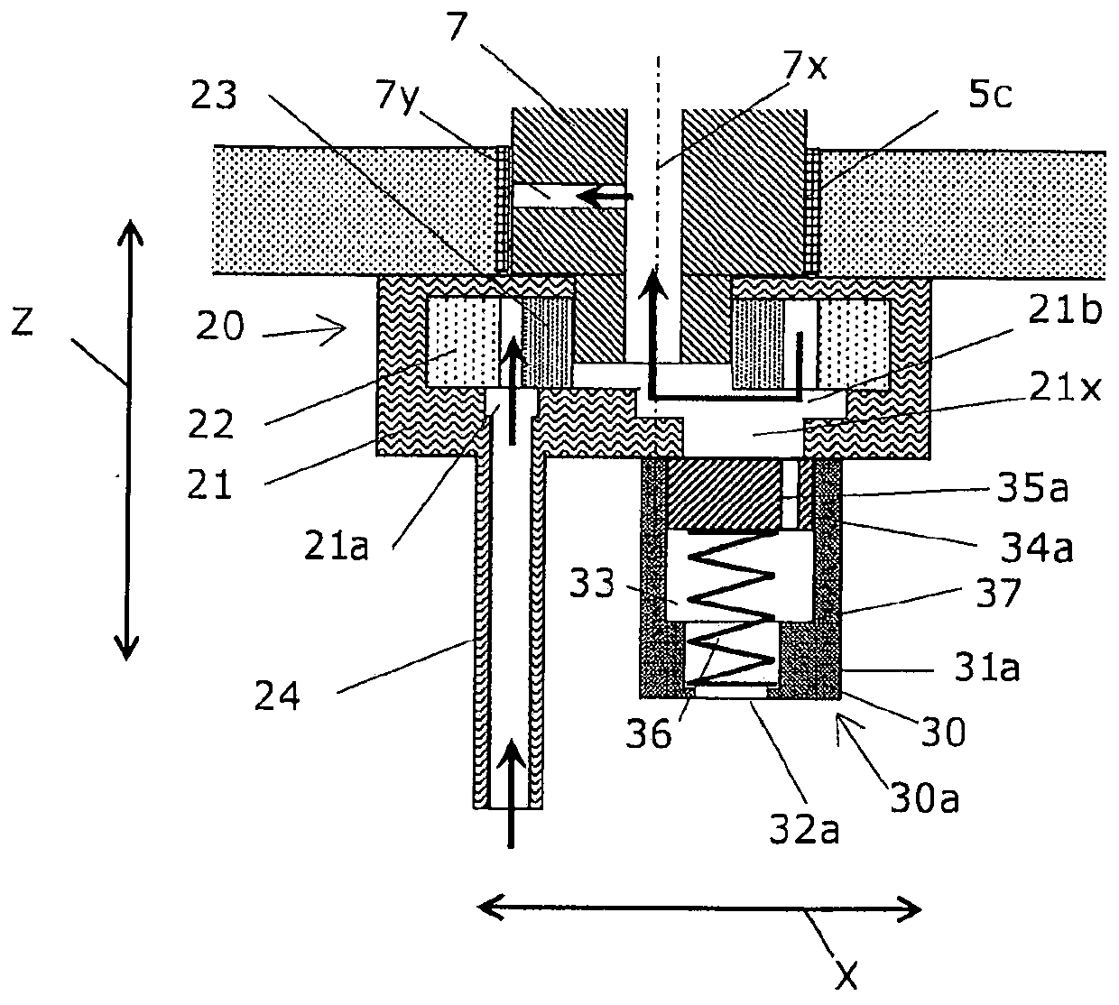
[0074] Figure 7 It is a schematic longitudinal sectional view showing a compressor according to Embodiment 2 of the present invention. Next, compressor 200 according to Embodiment 2 of the present invention will be described. The compressor 200 according to Embodiment 2 of the present invention differs from the compressor 100 according to Embodiment 1 of the present invention only in the structure of the differential pressure oil supply mechanism 30a.

[0075] Figure 8 It is a schematic diagram showing the behavior of the differential pressure oil supply mechanism when the rotational speed of the compressor according to Embodiment 2 of the present invention is lower than the first rotational speed threshold value N1. Figure 9 It is a sectional view showing the behavior of the differential pressure oil supply mechanism when the rotational speed of the compressor according to Embodiment 2 of the present invention is equal to or greater than the first rotational speed thresh...

Embodiment approach 3

[0090] Figure 12 It is a cross-sectional view of a pressure differential oil supply mechanism of a compressor according to Embodiment 3 of the present invention.

[0091] Next, compressor 300 according to Embodiment 3 of the present invention will be described. The compressor 300 according to Embodiment 3 of the present invention differs from the compressor 200 according to Embodiment 2 of the present invention only in the shape of the casing 31b, which is the case where the shape of the valve body 34b is cylindrical. First, refer to Figure 12 , the structure of the differential pressure oil supply mechanism 230a of the compressor 300 according to Embodiment 3 of the present invention will be described. In addition, pairs with Figure 1 to Figure 11 Parts having the same configuration as the compressors are denoted by the same reference numerals, and description thereof will be omitted.

[0092] A differential pressure oil supply mechanism 230a is provided below the oil ...


PUM


Abstract

The compressor comprises a differential pressure oil supply mechanism which is separately disposed from an oil supply pump and which has an oil supply passage through which oil in an oil reservoir space is introduced into an oil feed passage by use of a pressure difference between the oil reservoir space and the oil feed passage. The oil supply passage of the differential pressure oil supply mechanism communicates with an oil inlet / outlet located on the discharge side of the oil supply pump, and has a valve mechanism. The valve mechanism shuts off the oil supply passage when the difference between the pressure at the discharge side of the oil supply pump with respect to the pressure of the oil reservoir space is equal to or larger than a predetermined value, and opens the oil supply passage when the difference with respect to the pressure of the oil reservoir space is smaller than the predetermined value.

Description

technical field [0001] The invention relates to a compressor provided with an oil supply pump. Background technique [0002] Conventionally, there is known a compressor that includes: a closed container that collects oil at the bottom, a drive shaft that has an oil supply path inside, a compression mechanism that compresses fluid through rotation of the drive shaft, and a drive shaft provided on the drive shaft. The lower end of the shaft is an oil supply pump that supplies oil stored in an oil storage space provided in a low-pressure gas environment to the suction side space of the compression mechanism through an oil supply path (for example, refer to Patent Document 1). In this compressor, when the rotational speed becomes too low, the amount of oil supplied from the bottom via the oil supply path becomes insufficient, and the sealing performance of the compression mechanism part may decrease, resulting in an increase in leakage loss. [0003] In order to improve the pro...

Claims


Application Information

Patent Timeline
Patent Type & Authority Patents(China)
IPC IPC(8): F04C29/02F04B39/02F04C18/02
CPCF04B39/02F04C18/02F04C29/02
Inventor 北川秀明关屋慎角田昌之河村雷人诸江将吾
Owner MITSUBISHI ELECTRIC CORP
Why Eureka
Try Eureka