Linear boring tool capable of achieving variable feeding cutting

A boring tool and linear technology, applied in the field of engine crankshaft hole processing equipment, can solve the problems of uncontrollable spring feed force and unavoidable blade performance, etc., to improve surface quality, improve performance and life, and prevent tool collapse

Active Publication Date: 2019-04-05
ZHUZHOU CEMENTED CARBIDE CUTTING TOOLS CO LTD
View PDF5 Cites 2 Cited by
  • Summary
  • Abstract
  • Description
  • Claims
  • Application Information

AI Technical Summary

Problems solved by technology

[0003] The U.S. patent document with publication number US5865573AI discloses a kind of boring cutter with kinematic action itself. The kinematic mode of this knives has applied a spring to provide feed force, and the feed provided by the kinematic action of this knives is variable. Yes, but the feed force given by the spring is uncontrollable, so the performance of the blade of this kind of tool has to achieve the best and stable performance during cutting

Method used


Image

  • Linear boring tool capable of achieving variable feeding cutting
  • Linear boring tool capable of achieving variable feeding cutting
  • Linear boring tool capable of achieving variable feeding cutting

Examples


Embodiment Construction

[0023] The present invention will be described in further detail below in conjunction with the accompanying drawings and specific embodiments.

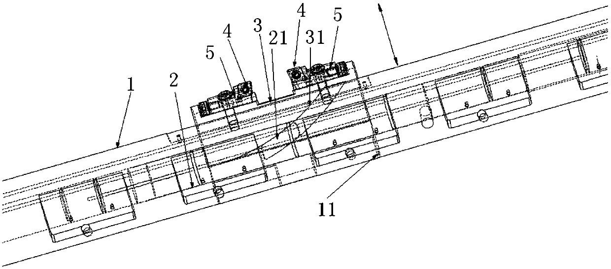
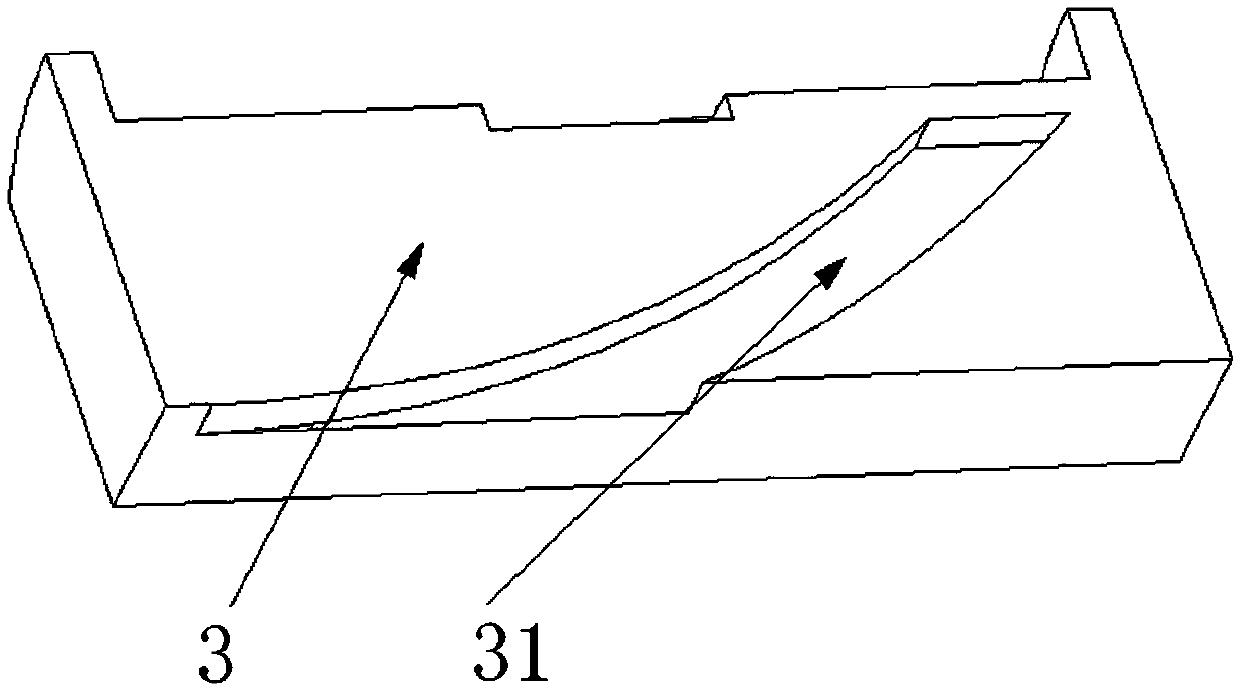
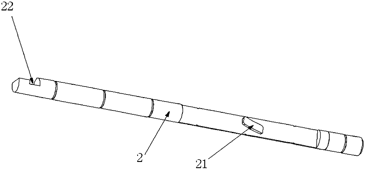
[0024] Such as Figure 1 to Figure 4 As shown, the linear boring tool that can realize variable feed cutting in this embodiment includes the outer tool body 1 of the linear boring tool, the inner tie rod 2 of the linear boring tool and the turning displacement block 3, and the inner tie bar 2 of the linear boring tool is set on the linear boring tool Inside the outer cutter body 1, the outer cutter body 1 of the linear boring tool is provided with a matching groove 11 for inserting the turning displacement block 3 on the circumferential surface, and the turning displacement block 3 is provided with an arc groove 31, and the inner pull rod 2 of the linear boring tool It is provided with a boss 21 that can slide in the arc groove 31 and drive the turning displacement block 3 to move radially along the outer cutter body 1 of the linear b...


PUM


Abstract

The invention discloses a linear boring tool capable of achieving variable feeding cutting. A linear boring tool outer tool body, a linear boring tool inner pull rod and a turning displacement block are included. The linear boring tool inner pull rod is sleeved with the linear boring tool outer tool body. The circumferential face of the linear boring tool outer tool body is provided with a matching groove in which the turning displacement block is inserted. The turning displacement block is provided with an arc groove. The linear boring tool inner pull rod is provided with a boss capable of sliding in the arc groove and driving the turning displacement block to move in the radial direction of the linear boring tool outer tool body. The part, protruding out of the matching groove, of the turning displacement block is provided with two symmetrically-arranged turning blades. The circle center of the arc groove and the turning blades are located on the same side. During bent shaft hole third thrust face turning through the linear boring tool, turning feeding becomes high from low and conforms to the specific curvature change, tool breakage at the cutting-in moment during turning is prevented, the performance of the turning blades is improved, the service life of the turning blades is prolonged, and the surface quality of the third thrust face turned by the linear boring tool is improved.

Description

technical field [0001] The invention relates to engine crankshaft hole machining equipment, in particular to a linear boring tool capable of variable feed cutting. Background technique [0002] Among the cutting tools used for metal processing, especially in the finishing of crankshaft holes of automobile engines, most manufacturers use linear boring tools for special machines in the field of crankshaft hole finishing. The processing content of this process is basically the first Boring the crankshaft hole, and then the linear boring tool converts the lateral displacement given by the machine tool into its own longitudinal displacement to turn the third thrust surface. In the prior art, the linear boring tool basically adopts the processing method of constant feed, rotation speed and linear speed when turning the third thrust surface, but the phenomenon of tool collapse often occurs at the moment of cutting the third thrust surface. The third thrust surface: The four-cylind...

Claims


Application Information

Patent Timeline
Patent Type & Authority Applications(China)
IPC IPC(8): B23B27/00
CPCB23B27/00
Inventor 付宇鹏刘敏李文学荣刚杨红星吕长江卞玲玲
Owner ZHUZHOU CEMENTED CARBIDE CUTTING TOOLS CO LTD
Why Eureka
Try Eureka