Precision machine tool spindle cooling system and centralized heat dissipation method based on heat conduction channel

A technology of precision machine tools and heat dissipation methods, applied in metal processing machinery parts, metal processing equipment, maintenance and safety accessories, etc., can solve the problems of limited cooling efficiency, increased difficulty and cost, and achieve temperature rise and thermal deformation, improve The effect of heat dissipation intensity and good engineering application prospect

Active Publication Date: 2020-07-28
XI AN JIAOTONG UNIV
View PDF9 Cites 0 Cited by
  • Summary
  • Abstract
  • Description
  • Claims
  • Application Information

AI Technical Summary

Problems solved by technology

[0004] However, when using the spindle housing for cooling, it is necessary to add a cooling jacket to the spindle housing, the cooling efficiency is limited, and when the coolant circulates inside the spindle system, heat will inevitably be transferred to other components such as the sleeve and the spindle housing , causing certain thermal deformation; when the hollow spindle is used for cooling, an additional rotary joint is required, which increases the difficulty and cost of design and assembly

Method used


Image

  • Precision machine tool spindle cooling system and centralized heat dissipation method based on heat conduction channel
  • Precision machine tool spindle cooling system and centralized heat dissipation method based on heat conduction channel
  • Precision machine tool spindle cooling system and centralized heat dissipation method based on heat conduction channel

Examples


Embodiment Construction

[0044] Below in conjunction with accompanying drawing, the present invention will be further described:

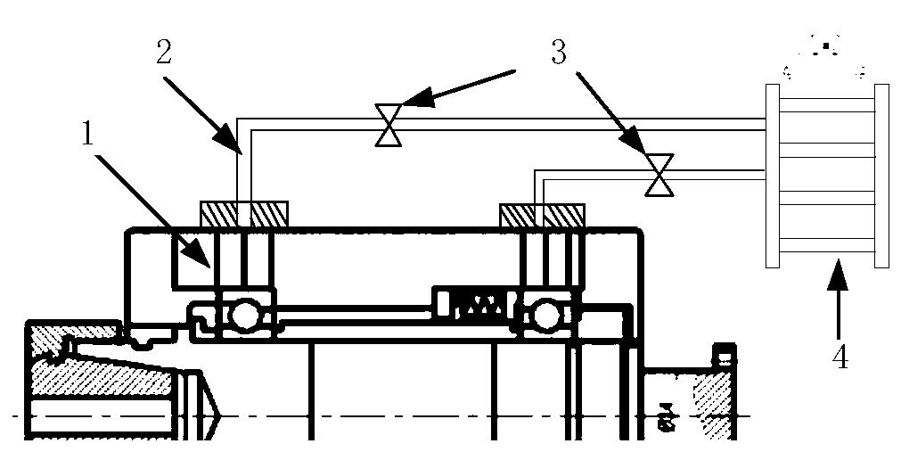
[0045] Such as figure 1 As shown, a precision machine tool spindle cooling system based on heat conduction passages of the present invention includes heat conduction passages 1 , cooling pipes 2 , valves 3 and cooling devices 4 . The heat conduction channel 1 is constructed along the radial direction according to the temperature field distribution at the bearings at both ends of the mechanical spindle. The basic principle of construction is that the heat conduction channel 1 must be constructed at the place with the highest temperature at both ends of the mechanical spindle. The higher the temperature, the denser the arrangement of the heat conduction channels. The number of is proportional to the temperature at the bearing, and the specific arrangement can be determined by formula (3) and the basic basis of the specific arrangement.

[0046] The basic basis for the speci...


PUM


Abstract

The invention discloses a heat conduction passage-based cooling system and centralized heat dissipation method for a spindle of a precision machine tool. The cooling system comprises heat conduction passages, a cooling pipeline, valves and a heat dissipation device; in allusion to a mechanical spindle and a motorized spindle of the precision machine tool, the heat conduction passages are established in bearing blocks and a spindle shell in a radial direction and a high-efficiency heat conduction material fills each heat conduction passage, and thus, the emitted heat of each internal heat source can be rapidly and efficiently transmitted to the outside of the spindle in a manner of heat conduction, and then centralized cooling is performed; and by taking maximization of heat dissipation intensity as a target, the reasonable layout of the heat conduction passages is determined according to different temperature fields in the axial direction and the circumferential direction of each of bearings at the front end and the rear end of the spindle and in the axial direction and the circumferential direction of a motor so as to achieve a balance between temperature rises in the axial direction and the circumferential direction of a spindle system and room temperature. The cooling system and centralized heat dissipation method disclosed by the invention are capable of overcoming abuses that efficiency is low, and the heat still can be absorbed by the spindle shell and installation parts by employing a traditional heat dissipation method, and have a better engineering application prospect.

Description

technical field [0001] The invention relates to the field of cooling and heat dissipation of machine tool spindles, in particular to a precision machine tool spindle cooling system and a centralized heat dissipation method based on heat conduction channels. Background technique [0002] With the continuous development of my country's industrial technology, the requirements for the accuracy of machine tools are also constantly increasing. The high-power spindle system configured on the precision machine tool ensures the high speed and high efficiency of the machine tool. However, when the machine tool spindle rotates at high speed, the friction between the rolling body of the bearing and the inner and outer rings of the bearing, and the loss of the stator and rotor of the built-in motor will generate a lot of heat. The heat propagates to various parts of the main shaft at different speeds in different directions, resulting in an unevenly distributed temperature field within t...

Claims


Application Information

Patent Timeline
Patent Type & Authority Patents(China)
IPC IPC(8): B23Q11/12
CPCB23Q11/127
Inventor 李旸赵万华张俊苏东旭
Owner XI AN JIAOTONG UNIV
Why Eureka
Try Eureka