Optical fiber plastic coating anti-jitter fiber pay-off device and system

An anti-shake, optical fiber technology, which is applied in the field of optical fiber sleeve plastic production, can solve the problems of increasing the optical fiber jitter amplitude, lengthening the route, and increasing the number of pay-off racks, etc., to improve the anti-shake effect, solve the jitter problem, and realize the optical fiber stable effect

Pending Publication Date: 2019-04-05
JIANGSU HENGTONG PHOTOELECTRIC
View PDF0 Cites 0 Cited by
  • Summary
  • Abstract
  • Description
  • Claims
  • Application Information

AI Technical Summary

Problems solved by technology

The optical fiber reel only rotates on the pay-off frame without axial movement. The width of the optical fiber reel itself is relatively large, which cannot be ignored. This makes the distance between the two sides of the reel and the dancing tension guide wheel must be greater than the distance between the middle of the reel and the dancing tension guide wheel. Distance, during the payout process, the payout distance is constantly changing, while the payout speed remains unchanged. Therefore, the mismatch between the distance and the speed makes the optical fiber vibrate during payout, and the larger the width of the reel, the greater the vibration amplitude. In addition, in the production process of the multi-core sleeve, due to the large number of optical fibers, the number of pay-off racks required also increases accordingly, which makes the route of the optical fiber from the pay-off rack to the extrusion head longer. Increased fiber jitter amplitude

Method used


Image

  • Optical fiber plastic coating anti-jitter fiber pay-off device and system
  • Optical fiber plastic coating anti-jitter fiber pay-off device and system
  • Optical fiber plastic coating anti-jitter fiber pay-off device and system

Examples


Embodiment 1

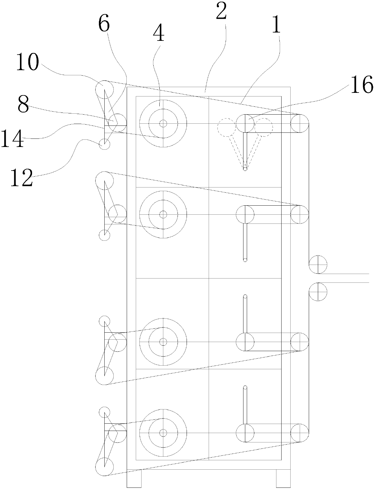
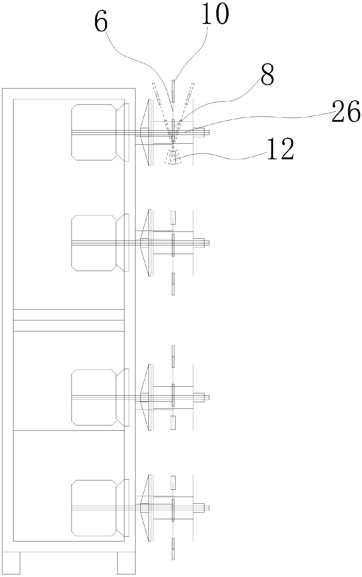
[0023] Such as figure 1 , as shown in 2, this embodiment discloses an anti-vibration fiber pay-off device for optical fiber sheathing, including a pay-off frame 2, an optical fiber reel 4 and a dancing tension guide wheel 16, and the above-mentioned optical fiber reel 4 passes through the pay-off shaft Installed on the pay-off frame 2, and rotate the fiber with the above-mentioned pay-off shaft, the swing guide wheel assembly is also installed on the above-mentioned pay-off frame 2, the above-mentioned swing guide wheel assembly includes a balance wheel bracket 6, and is installed on the above-mentioned balance wheel The first fiber guide wheel 8, the second fiber guide wheel 10 and the counterweight 12 on the support 6; the wheel axles of the first fiber guide wheel 8 and the second fiber guide wheel 10 are all arranged parallel to the disk axis of the fiber optic disk tool 4; The balance wheel bracket 6 is rotatably connected to the pay-off frame 2 through a swing shaft 26 ,...

Embodiment 2

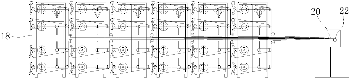
[0029] Such as image 3 , as shown in 4, this embodiment discloses an anti-shake fiber payout system for optical fiber sheathing, which cooperates with the production of multi-core optical fiber sheathing, including a mounting frame 18, an anti-shake fiber payout device with the above structure and a For the fiber collection guide wheel, several of the above-mentioned anti-shake fiber-spraying devices are sequentially installed on the above-mentioned installation frame 18 from top to bottom, or / and several of the above-mentioned anti-shake fiber-spraying devices are arranged sequentially along the optical fiber moving direction and installed on the above-mentioned on the mounting frame 18.

[0030] Specifically, in order to cooperate with the plastic production of multi-core optical fibers, the number of fiber releasing devices configured in the fiber releasing system is directly related to the number of optical fiber cores in the optical cable. A fiber pay-off device with th...


PUM


Abstract

The invention discloses an optical fiber plastic coating anti-jitter fiber pay-off device. The optical fiber plastic coating anti-jitter fiber pay-off device comprises a pay-off rack and optical fiberreels. The optical fiber reels are mounted on the pay-off rack and rotate along with pay-off shafts to pay off optical fibers. Swing guide wheel assemblies are mounted on the pay-off rack. Each swingguide wheel assembly comprises a swing wheel bracket, an optical fiber guide wheel I, an optical fiber guide wheel II and a counter weight, wherein the optical fiber guide wheel I, the optical fiberguide wheel II and the counter weight are all mounted on the swing wheel bracket; the swing wheel bracket is mounted on the pay-off rack through bearings and can swing in the direction parallel to theaxial direction of the corresponding optical fiber reel; the connection lines of the centers of the optical fiber guide wheel I, the optical fiber guide wheel II and the counter weight form a triangle structure; and the optical fiber on the corresponding optical fiber reel are guided by the optical fiber guide wheel I and the optical fiber guide wheel II to be output. The optical fibers are paidoff and output through the optical fiber reels and are guided and output through the swing guide wheel assemblies to be fed into a plastic extruding machine head during the plastic coating process. Through the design of the swing guide wheel assemblies, the lengths of the optical fibers from the optical fiber reels to dancing tension guide wheels can be made consistent. The problem of jittering ofoptical fibers in the pay-off process in the prior art is solved.

Description

technical field [0001] The invention relates to the technical field of optical fiber sheathing production technology, in particular to an anti-shake fiber payout device for optical fiber sheath molding, and also relates to a fiber payout system using the anti-shake fiber payout device. Background technique [0002] At present, in the production process of the molding process, the optical fiber pay-off is directly released from the optical fiber reel, and then directly introduced into the extruder head through the dancing tension guide wheel to the transition guide wheel to change the direction. The optical fiber reel only rotates on the pay-off frame without axial movement. The width of the optical fiber reel itself is relatively large, which cannot be ignored. This makes the distance between the two sides of the reel and the dancing tension guide wheel must be greater than the distance between the middle of the reel and the dancing tension guide wheel. Distance, during the ...

Claims


Application Information

Patent Timeline
IPC IPC(8): B29C48/285B29C48/154B29L11/00
CPCB29L2011/0075Y02P40/57
Inventor 刘诚顾利国李惠强吴斌华濮志豪李伟林陈张鑫元吴水荣张萍
Owner JIANGSU HENGTONG PHOTOELECTRIC
Why Eureka
Try Eureka