Deep water oil and gas well overflow monitoring method

A technology for oil and gas wells and overflows, which is used in earth-moving drilling, flushing wellbore, wellbore/well components, etc. Time-sensitive effect

Active Publication Date: 2019-04-05
SOUTHWEST PETROLEUM UNIV
View PDF13 Cites 2 Cited by
  • Summary
  • Abstract
  • Description
  • Claims
  • Application Information

AI Technical Summary

Problems solved by technology

For example, "China Offshore Oil and Gas", Volume 28, Issue 1, 2016 "Research on Ultrasonic Gas Intrusion Real-time Monitoring Technology of Deepwater Drilling Riser", this method installs an ultrasonic device at the riser joint to measure the flow in the riser in real time. Downhole overflow monitoring, but this method has low measurement accuracy, is greatly disturbed by drilling tools, and has high cost, and it is only for riser gas intrusion monitoring

Method used


Image

  • Deep water oil and gas well overflow monitoring method
  • Deep water oil and gas well overflow monitoring method
  • Deep water oil and gas well overflow monitoring method

Examples


Embodiment 1

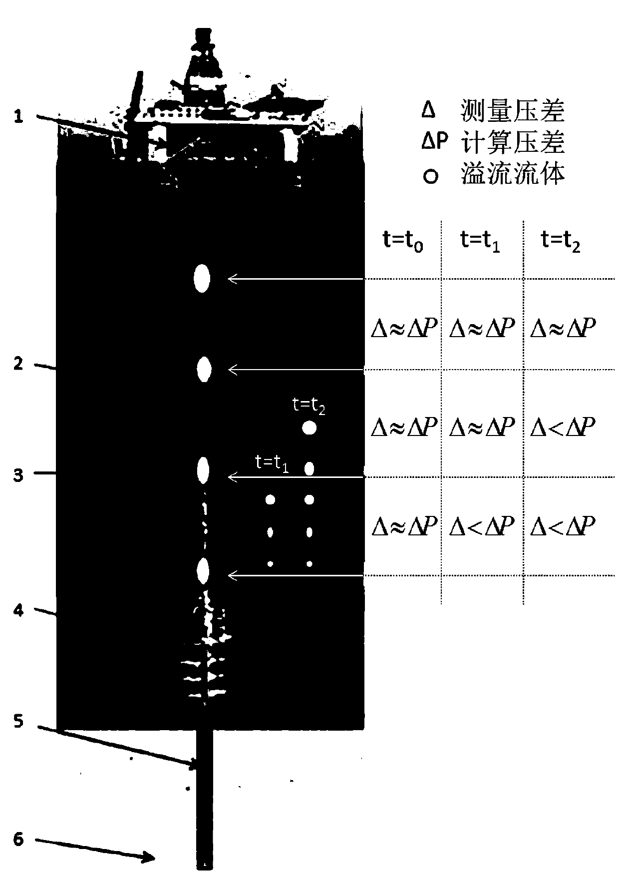
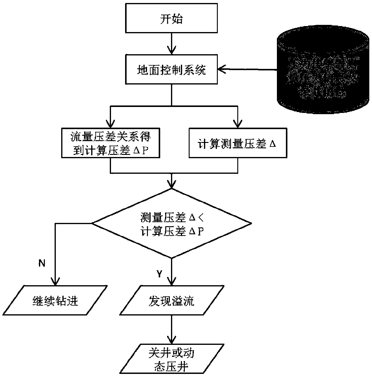
[0031] Such as figure 1 and figure 2 As shown, the pressure sensor 3 is installed on the riser 2 equidistantly according to the water depth to measure the fluid pressure in the riser annulus in real time. Then, the pressure information measured by the pressure sensor in real time is transmitted to the ground control system in real time. The pressure sensor measurement information is processed to obtain the measured pressure difference ΔP of two adjacent pressure sensors, which is compared with the calculated pressure difference ΔP obtained by real-time calculation of the relationship between flow and pressure difference, to judge and identify the degree of overflow, and to issue an alarm to provide reasonable well control measures .

[0032] Among them, when the water depth is less than 1000m, the pressure sensor arrangement interval is 50m; when the water depth is 1000-2000m, the pressure sensor arrangement interval is 100m; when the water depth is greater than 2000m, the p...


PUM


Abstract

The invention discloses a deep water oil and gas well overflow monitoring method. The deep water oil and gas well overflow monitoring method comprises the following steps: equidistantly mounting pressure sensors on a water spacing tube according to water depth, measuring circular fluid pressure in the water spacing tube in real time, then transmitting pressure information which is measured by thepressure sensors in real time to a ground control system, and processing and analyzing the measured information of the pressure sensors of the water spacing tube by the ground system to obtain measurement pressure difference between the two adjacent sensors. According to the ground system, drilling fluid is pumped in through a wellhead, the pressure difference between the two adjacent sensors is obtained in combination with a flow and pressure difference relation, the pressure difference measured by the pressure sensors is compared with the pressure difference calculated by the flow and pressure difference relation, overflow in the water spacing tube is monitored and recognized, an alarm is given, and a reasonable well control measure is provided. Underground early overflow monitoring precision is improved, underground early overflow can be recognized in time, the position of overflow fluid in the water spacing tube is determined, the reasonable well control measure is taken, and saferunning of drilling of oil and gas wells is ensured.

Description

technical field [0001] The invention belongs to the technical field of production safety monitoring in oil and gas drilling engineering, and in particular relates to a deep water oil and gas well overflow monitoring method. Background technique [0002] At present, during the drilling of deepwater oil and gas wells, due to the special marine environment, deepwater well control is affected by drilling water depth, deep water low temperature, natural gas hydrates, long choke pipelines, and narrow drilling fluid safe density window. Shallow water drilling well control and land drilling well control are more complex and riskier. Therefore, more effective well control measures are required for deepwater drilling, and the most effective well control measure is early monitoring of downhole overflow. It continues to happen, eventually leading to uncontrollable overflow, and even blowout accidents, causing huge economic losses, casualties and marine pollution. In order to ensure th...

Claims


Application Information

Patent Timeline
Patent Type & Authority Applications(China)
IPC IPC(8): E21B21/08E21B47/117G08B21/12
CPCE21B21/08E21B47/117G08B21/12
Inventor 唐弢马天寿陈平李枝林付建红王旭东张杰郭昭学
Owner SOUTHWEST PETROLEUM UNIV
Why Eureka
Try Eureka