Vacuum pump

A technology for vacuum pumps and bearing chambers, applied to pumps, pump components, rotary piston pumps, etc., can solve the problems that cannot be used in IC equipment, high power consumption, low ultimate vacuum, etc., achieve long service life, save energy and space , reduce the effect of pulsation impact

Inactive Publication Date: 2019-04-05
石静轩
View PDF0 Cites 0 Cited by
  • Summary
  • Abstract
  • Description
  • Claims
  • Application Information

AI Technical Summary

Problems solved by technology

[0004] In order to overcome the shortcomings of the existing Roots pump technology, such as low ultimate vacuum, high power consumption, large volume, and inability to be used in IC equipment, the present invention provides a Roots vacuum pump, a new type of Roots dry pump suitable for IC equipment

Method used


Image

  • Vacuum pump
  • Vacuum pump
  • Vacuum pump

Examples


Embodiment Construction

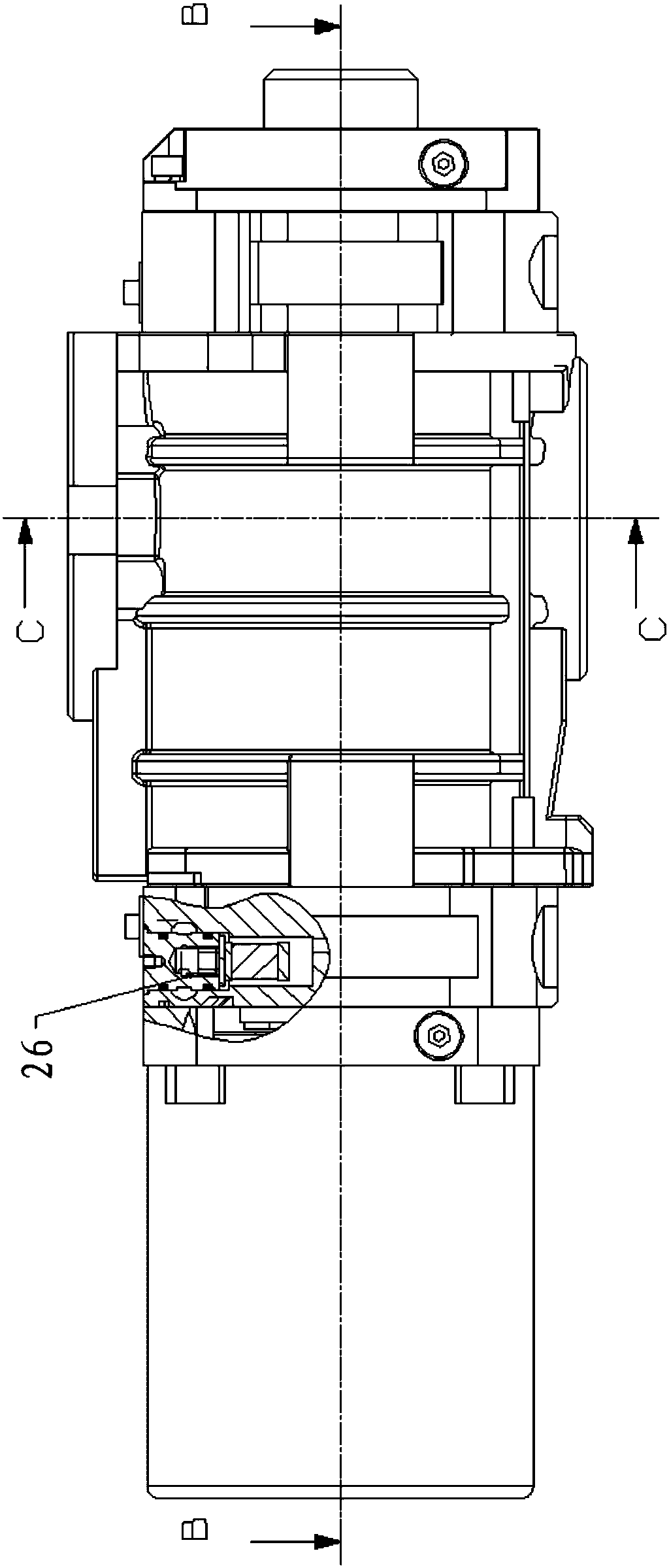
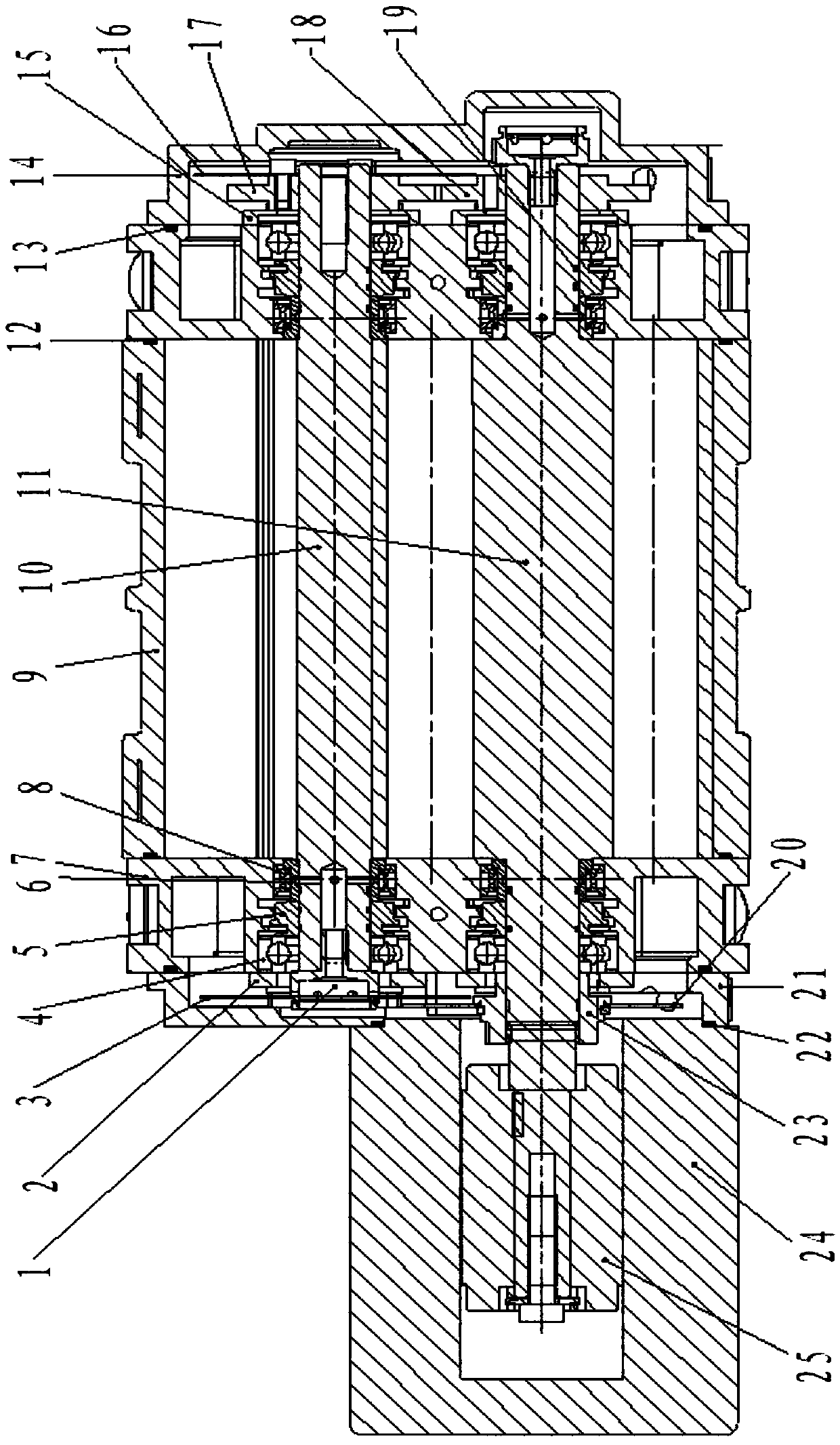
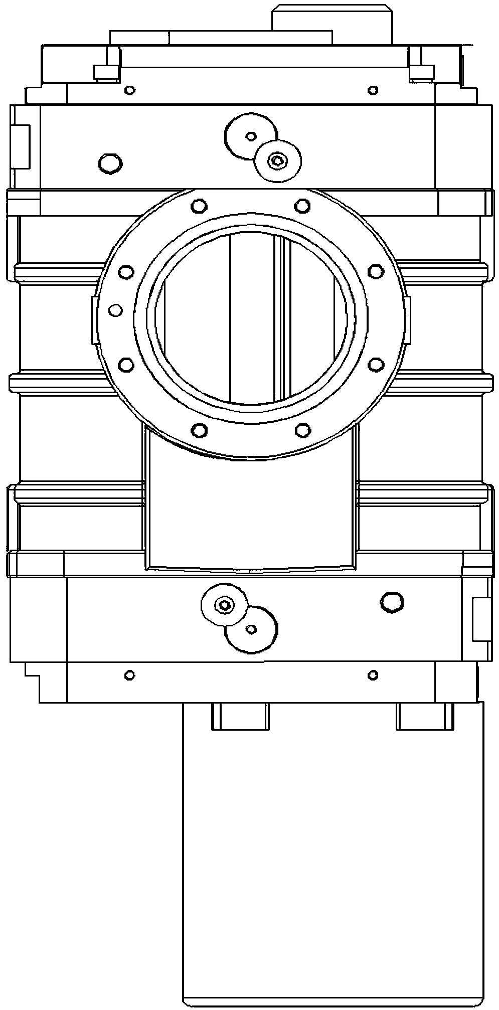
[0017] like Figure 1-Figure 4 As shown, the present invention includes a shaft end fixing nut 1, a motor side bearing gland 2, a motor side driven oil throwing pan 3, a bearing 4, a bearing support ring 5, a shaft seal ring 6, a bearing cavity 7, and a double-lip shaft seal 8 , Roots cavity 9, driven rotor shaft 10, driving rotor shaft 11, sealing ring 12, sealing ring 13, gear cavity 14, gear side bearing gland 15, gear side driven oil thrower 16, driven gear 17 , driving gear 18, rectangular sealing ring 19, driving oil throwing plate 20, motor cavity 21, motor sealing ring 22, driving bushing 23, rotor shaft shielding frequency conversion motor 24, motor rotor 25, oil-gas separation device 26, Roots cavity 9 The bearing cavity 7 and the gear cavity 14 are installed at both ends, the bearing 4, the bearing support ring 5, and the double-lip shaft seal 8 are installed in the bearing cavity 7 bearing seat and the gear cavity bearing cavity bearing seat in turn, and the motor ...


PUM


Abstract

The invention discloses a vacuum pump. Bearing cavities and gear cavities are formed in the two sides of a roots cavity. Motor cavities are connected with the bearing cavities. Shaft sealing devices are arranged between the bearing cavities and the roots cavity as well as between the roots cavity and the gear cavities correspondingly. The shaft sealing devices are arranged on a driving rotor shaftand a driven rotor shaft. Motors are rotor shaft shield variable frequency motors. The bearing cavities and the gear cavities are each provided with a lubricating device. Oil-gas separation devices are arranged in the bearing cavities in the two ends. The vacuum pump is small in size and high in pumping speed, and energy and space are saved. Variable frequency speed control is conducted, and service life is long. Teflon double-lip shaft seals are adopted, and the maintenance period of the pump is prolonged. The oil-gas separation devices are adopted, and the leakage problem of oil vapor to avacuum chamber is solved. The structure that motor rotors and a pump shaft are integrated, and motor stators are outside an oil chamber is adopted, motor dynamic sealing and motor vibration problems are solved, a heat expansion assembly structure is adopted for gear assembly, and the unbalance degree and vibration of a motion part are reduced.

Description

technical field [0001] The invention relates to the technical field of vacuum pumps, in particular to a Roots vacuum pump. Background technique [0002] Roots vacuum pumps evolved from Roots blowers, including high vacuum multistage Roots pumps, medium vacuum Roots booster pumps and dry Roots pumps with direct exhaust to the atmosphere. They are widely used in chemical industry, papermaking, metallurgy, film preparation, Food and other industries are also commonly used in the IC equipment industry as a vacuum pump. The research and manufacture of Roots vacuum pumps in China was earlier, but there are not many Roots dry pumps suitable for the strict requirements of the IC equipment industry, resulting in long-term dependence on imports for this equipment. [0003] The air-cooled Roots dry pump meets many requirements of the IC equipment industry, such as high working temperature, long-term stable operation, low noise, simple maintenance, clean and oil-free, etc. It is a dry ...

Claims


Application Information

Patent Timeline
Patent Type & Authority Applications(China)
IPC IPC(8): F04C18/18F04C23/02F04C25/02F04C27/00F04C29/02F04C29/06
CPCF04C18/18F04C23/02F04C25/02F04C27/009F04C29/02F04C29/026F04C29/06
Inventor 石静轩
Owner 石静轩
Why Eureka
Try Eureka