Single-soldier rocket launching system capable of being used in limited space

A rocket launch, limited space technology, applied in rocket launch devices, offensive equipment, weapon types, etc., can solve problems such as shooter damage, reduce flame temperature, reduce initial ignition pressure peak, and ensure safety.

Pending Publication Date: 2019-04-05
北京恒星箭翔科技有限公司
View PDF0 Cites 2 Cited by
  • Summary
  • Abstract
  • Description
  • Claims
  • Application Information

AI Technical Summary

Problems solved by technology

[0003] When an individual rocket powered by a recoilless gun is launched in a limited space, while the high-pressure gas produced by the artillery pushes the rocket out

Method used


Image

  • Single-soldier rocket launching system capable of being used in limited space
  • Single-soldier rocket launching system capable of being used in limited space
  • Single-soldier rocket launching system capable of being used in limited space

Examples


Embodiment 1

[0030] Embodiment 1, see attached figure 1 , a kind of individual rocket launching system that can be used in limited space, it comprises: rocket launcher 8, rocket warhead 9 and rocket engine combustion chamber 10;

[0031] See attached figure 2 , 3 , 4, the rocket engine combustion chamber 10 comprises: engine housing 14, tube type solid charge 2, charge fixed plate 12, special-shaped nozzle 3 and integral igniter plugging structure 7; tube type solid charge 2 adopts low A thin-walled porous solid propellant grain with a high burning rate; the surface of the charge fixing plate 12 is provided with a vent hole matching the tubular solid charge 2, and an air passage structure is provided at the edge of the charge fixing plate 12, The charge fixing plate 12 has air pressure balance capability; the special-shaped nozzle 3 includes: a circular convergent section, a spray throat and a binary expansion section; the integrated igniter blocking structure 7 includes: an ignition ca...

Embodiment 2

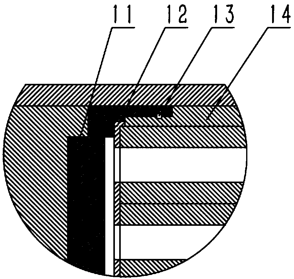
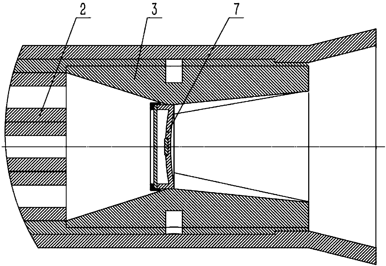
[0034] Embodiment 2, see attached Figure 5 , 6 , 7, on the basis of embodiment 1, further, at the afterbody of rocket launcher 8, also be provided with silencer sleeve 1; Structure 6; wherein: the muffler shell 4 is installed at the tail of the rocket launcher 8, the sound-absorbing interlayer 5 in the barrel is bonded to the inner wall of the muffler shell 4, and the micro-hole plate sound-absorbing structure 6 is installed in the sound-absorbing interlayer 5 in the barrel and passed through The built-in slot of the muffler housing 4 is used for positioning, and the microporous plate muffler structure 6 is provided with a built-in gas channel.

[0035] Further, the binary expansion section of the special-shaped nozzle 3 has a structure of oblique diversion ribs; the exit eaves of the binary expansion section of the special-shaped nozzle 3 is provided with a sawtooth sound-absorbing structure.

[0036]The oblique guide rib structure of the special-shaped nozzle 3 can make t...


PUM


Abstract

The invention relates to the technical field of anti-tank weapons, in particular to a single-soldier rocket launching system. The technical scheme of the single-soldier rocket launching system capableof being used in a limited space is that a rocket engine combustion chamber comprises an engine shell, a tubular solid explosive, an explosive loading fixing plate, a special-shaped spray pipe and anintegrated igniter plug cover structure; the surface of the explosive loading fixing plate is provided with a vent hole matched with the tubular solid explosive, and an air passing groove structure is arranged at the edge part; the special-shaped spray pipe comprises a circular convergence section, a spray throat and a binary expansion section; the integrated igniter plug cover structure comprises a ignition powder box and an aluminum plug cover; the integrated igniter plug cover structure is installed at the spray throat of the special-shaped spray pipe; a rocket projectile fighting part isconnected to an engine front end socket through threads, the engine front end socket is connected to the engine shell through a shear pin, and the explosive loading fixing plate is in glue connectionwith the engine front end socket and the tubular dolid explosive; and the special-shaped spray pipe is fixedly installed in the tail part of the engine shell. According to the system, the safety of ashooter and the shooting invisibility are ensured.

Description

technical field [0001] The invention relates to the technical field of anti-tank weapons, in particular to an individual rocket launching system. Background technique [0002] In a complex battlefield environment, in order to complete various strike tasks, the portable individual rocket should have good adaptability to the battlefield environment and the ability to shoot in small spaces and houses. With the development of weapons and equipment technology, many countries in the world have put forward requirements for the ability of portable anti-tank weapons to be able to shoot in narrow fortifications such as streets, alleys, houses, caves and field fortifications with roofs. [0003] When an individual rocket powered by a recoilless gun is launched in a limited space, while the high-pressure gas produced by the artillery pushes the rocket out of the muzzle, a large amount of gas is discharged from the tail nozzle, which may cause noise, harmful gas and tail flames. Causes ...

Claims


Application Information

Patent Timeline
IPC IPC(8): F41F3/04
CPCF41F3/04
Inventor 李世鹏官典陈琪王斯强
Owner 北京恒星箭翔科技有限公司
Why Eureka
Try Eureka