Scattering type near-field micro-optical system based on transmitting method

A near-field microscopy and optical system technology, applied in the field of precision instruments, can solve the problems of system signal-to-noise ratio to be improved, poor resolution, background noise and mutual interference of lighting receiving optical paths, etc., to achieve near-field signal generation and scattering Signal extraction, realization of irrelevance, realization of re-collection and focusing effects

Pending Publication Date: 2019-04-05
HUAZHONG PHOTOELECTRIC TECH INST (CHINA SHIPBUILDING IND CORP THE NO 717 INST)
View PDF12 Cites 3 Cited by
  • Summary
  • Abstract
  • Description
  • Claims
  • Application Information

AI Technical Summary

Problems solved by technology

The practicality and popularization of the former needs to solve the problem of the size of the signal first, that is, how to effectively localize and enhance the anti-reflection of the terahertz wave; the latter is accompanied by the diffraction of the evanescent field, so it is necessary to solve the control of the near-field distance and the control of the terahertz wave. High-efficiency coupling and conversion, and low terahertz wave transmittance, but there are many shortcomings such as background noise and mutual interference of lighting receiving optical paths, the signal-to-noise ratio of the system needs to be improved, and the resolution is generally not as good as the former
[0005] In the usual near-field imaging system, a beam splitter is used to generate and extract near-field signals, but it is difficult for the beam splitter to ensure consistent dispersion characteristics in the wide-band, which affects the performance of the near-field imaging system in the wide-band application

Method used


Image

  • Scattering type near-field micro-optical system based on transmitting method
  • Scattering type near-field micro-optical system based on transmitting method

Examples


Embodiment Construction

[0027] In order to make the object, technical solution and advantages of the present invention clearer, the present invention will be further described in detail below in conjunction with the accompanying drawings and embodiments. It should be understood that the specific embodiments described here are only used to explain the present invention, not to limit the present invention.

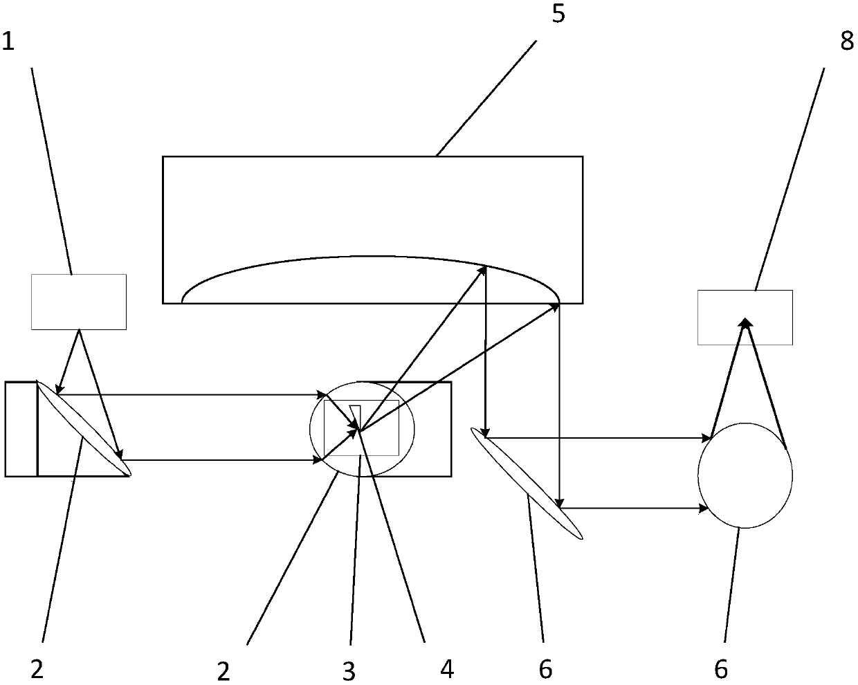
[0028] The present invention uses the form of a paraboloid or quadratic mirror to realize the re-collection and focusing of a wide range of scattered signals, and realizes that the measurement has nothing to do with samples and wavelengths, and realizes the generation of near-field signals in wide bands and the extraction of scattered signals .

[0029] like figure 1 , 2 As shown, the scattering near-field micro-optic system based on the transmission method in the embodiment of the present invention includes an illumination light source 1, a parabolic mirror group 2, a sample stage 3, a metal nan...


PUM


Abstract

The invention discloses a scattering type near-field micro-optical system based on a transmitting method. The scattering type near-field micro-optical system comprises an irradiating light source, a parabolic mirror set, a sample platform, a metal nanoneedle, a large-aperture parabolic mirror, a plane mirror set, a parabolic mirror and a detector; a to-be-detected sample is placed on the sample platform, and the metal nanoneedle is placed above the to-be-detected sample; light emitted by the irradiating light source is collimated to parallel light through the parabolic mirror set firstly and then converged under the sample platform, the light is transmitted to the to-be-detected sample form the sample platform, then scattering signals are excited from a needle tip of the metal nanoneedle and collected through the large-aperture parabolic mirror which is placed above the metal nanoneedle, the light is collimated and output, the collimated and output light is irradiated into the parabolic mirror through the plane mirror set, and finally the signals are converged to the detector. The scattering type near-field micro-optical system based on the transmitting method realizes generation of near field signals of broadband and extraction of scattering signals.

Description

technical field [0001] The invention relates to the technical field of precision instruments, in particular to a scattering near-field micro-optical system based on a transmission method. Background technique [0002] Near-field imaging is one of the research hotspots to break through the diffraction limit and obtain sub-wavelength resolution images. Since the idea was proposed, it has been verified in the fields of microwave, visible light, infrared and terahertz waves. [0003] The near field usually refers to the region where the distance is on the order of wavelength or even sub-wavelength. Typical terahertz wave near-field imaging refers to scanning near-field terahertz wave microscopy, that is, using local terahertz waves to perform two-dimensional grid-like scanning in the near-field area of ​​the sample. The computer processes and reconstructs the final image. The resolution of the image obtained in this process is not limited by the wavelength, but mainly depends o...

Claims


Application Information

Patent Timeline
Patent Type & Authority Applications(China)
IPC IPC(8): G01N21/47G01N21/01
CPCG01N21/01G01N21/47G01N2021/0112
Inventor 姚远耿安兵邹勇华章侃袁英豪郭劼周正李渊
Owner HUAZHONG PHOTOELECTRIC TECH INST (CHINA SHIPBUILDING IND CORP THE NO 717 INST)
Why Eureka
Try Eureka