
Multi-pulse-set optimization design method of space-based early warning radar

A technology of early warning radar and space-based radar, applied in the direction of reflection/re-radiation of radio waves, utilization of re-radiation, measurement devices, etc. Reduce the impact of transmit pulse occlusion and sub-satellite point occlusion, improve work efficiency, reduce distance blur clutter and distance detection blind spots

Active Publication Date: 2019-04-05
XIAN INSTITUE OF SPACE RADIO TECH
View PDF7 Cites 3 Cited by
  • Summary
  • Abstract
  • Description
  • Claims
  • Application Information

AI Technical Summary

Problems solved by technology

The space-based radar has a longer working distance. According to the traditional repetition frequency design, it will require more space filling time and greatly reduce the working efficiency of the radar. Therefore, measures need to be taken to reduce the space filling time; the space-based early warning radar has a larger clutter coverage area , which means that the range clutter ambiguity is more serious, and puts forward higher requirements for clutter suppression technology, so the repetition frequency design should minimize the range ambiguity clutter; the clutter spectrum is wider, and considering the target speed range, the space-based radar must ensure that the target has More Doppler visible areas; at the same time, the repetition frequency design also needs to minimize the influence of detection blind spots and sub-satellite point echoes
Therefore, the design of space-based early warning radar repetition frequency group is very complicated
[0007] At present, there is no relevant public literature on the design of space-based early warning radar repetition frequency group for high-speed targets in the air

Method used


Image

  • Multi-pulse-set optimization design method of space-based early warning radar
  • Multi-pulse-set optimization design method of space-based early warning radar
  • Multi-pulse-set optimization design method of space-based early warning radar

Examples


Embodiment Construction

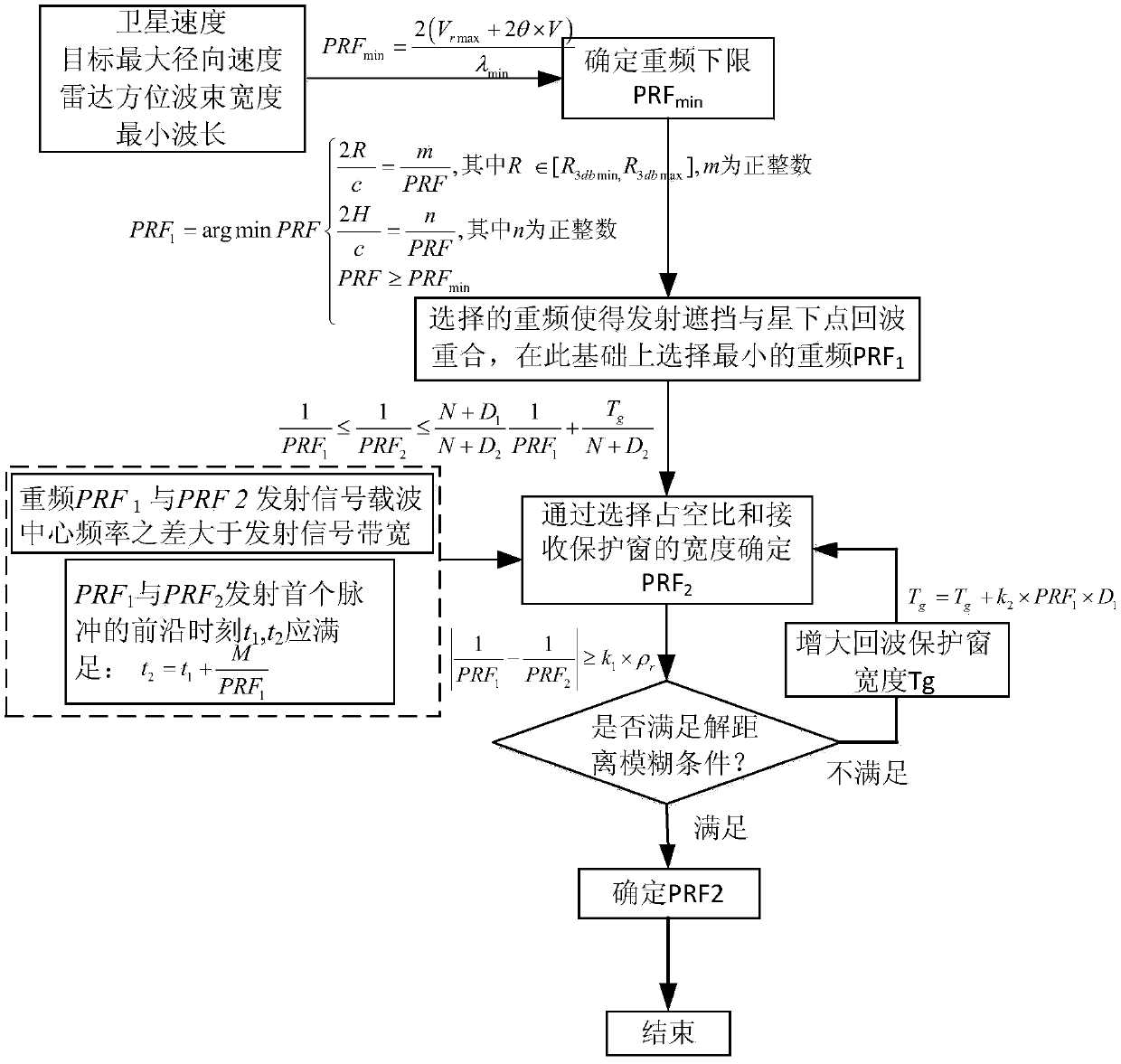
[0026] Such as figure 1 , the technical solution of the present invention is:

[0027] Step 1 The satellite orbit height is H, the satellite speed is V, the 3dB beamwidth of the radar azimuth antenna pattern is θ; the radar center frequency f range is [f min , f max ], the corresponding wavelength λ range is [λ min ,λ max ]; the pulse repetition frequency is expressed as PRF, the duty cycle is D, and the value range is [D min ,D max ]; the maximum radial velocity between the detection target and the radar is V rmax . Then the lower limit of repetition frequency selection can be calculated and determined as:

[0028]

[0029] According to the above formula, it can be seen that at this time, the repetition frequency only allows the target to be blurred once in velocity—velocity direction blurring, and cannot be blurred back to the main lobe clutter, so that the target will not be canceled when the clutter is suppressed.

[0030] Step 2 Design the first pulse repetitio...


PUM


Abstract

The invention provides a multi-pulse-set optimization design method of a space-based early warning radar, and belongs to the technical field of radar early warning. Various factors including target doppler ambiguity, range clutter ambiguity, range blind areas, space filling time, target range ambiguity resolving and speed ambiguity resolving are fully considered, while reliable target detection isensured, the influence of transmission pulse shielding and sub-satellite point shielding is lowered to the maximum extent, and therefore range ambiguity clutters and range detection blind areas are reduced. Specifically, through the design criteria of the minimum multi-pulse, while reliable target detection is ensured, the influence of transmission pulse shielding and sub-satellite point shielding is lowered to the maximum extent, and therefore the range ambiguity clutters and the range detection blind areas are reduced. The relation between a multi-pulse set and the duty ratio and the protecting window length is restrained, no space and time filling is required during switching of different multi-pulses of the space-based radar, and working efficiency of the radar is greatly improved.

Description

technical field [0001] The invention relates to a space-based early warning radar repetition frequency group optimization design method, which belongs to the technical field of radar early warning. Background technique [0002] At present, there is no space-based early warning radar in orbit. The related information of space-based early warning radar in public literature mainly focuses on the research on the concept and system of space-based early warning radar, clutter analysis and suppression, etc. According to the research, there is no special discussion Relevant literature on space-based early warning radar repetition group design. [0003] Repetition frequency and carrier frequency are both the transmitted signal properties of pulse radar. Repeat frequency refers to the number of pulses transmitted within one second, and the carrier frequency is the carrier frequency of the actual transmitted signal (if the transmitted signal is a sinusoidal signal and the pulse width ...

Claims


Application Information

Patent Timeline
IPC IPC(8): G01S13/88G01S7/41
CPCG01S7/41G01S7/414G01S13/88G01S13/886
Inventor 段崇棣王伟伟李渝杨晓超朱江黎薇萍范一飞李奇
Owner XIAN INSTITUE OF SPACE RADIO TECH
Learn More