Driving structure and periscope type camera module

A driving structure and mover technology, applied in electric components, image communication, TV and other directions, can solve the problems of inability to rotate in multiple dimensions, affecting the appearance of mobile phones, poor anti-shake effect, etc., to save time, adjust the function sensitively, reduce high effect

Pending Publication Date: 2019-04-05
DONGGUAN PRECISION PHOTONICS LTD
View PDF1 Cites 6 Cited by
  • Summary
  • Abstract
  • Description
  • Claims
  • Application Information

AI Technical Summary

Problems solved by technology

The periscope camera module of the above-mentioned patent document realizes the anti-shake effect through a rotatable prism. Poor; moreover, the thickne

Method used


Image

  • Driving structure and periscope type camera module
  • Driving structure and periscope type camera module
  • Driving structure and periscope type camera module

Examples


Embodiment 1

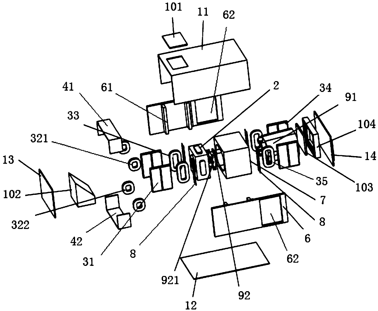
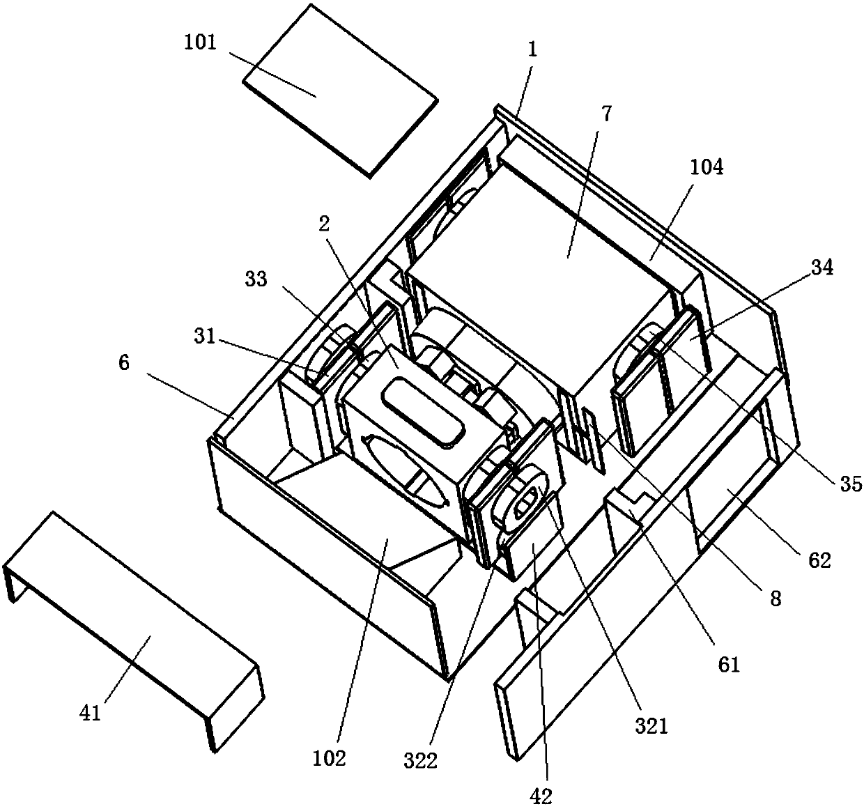
[0034] For the driving structure of this embodiment, refer to figure 1 - Figure 4 , including a seat body 1 , a carrier 2 , a drive assembly, a mounting frame 7 , a reset member 8 and a spacer 6 .

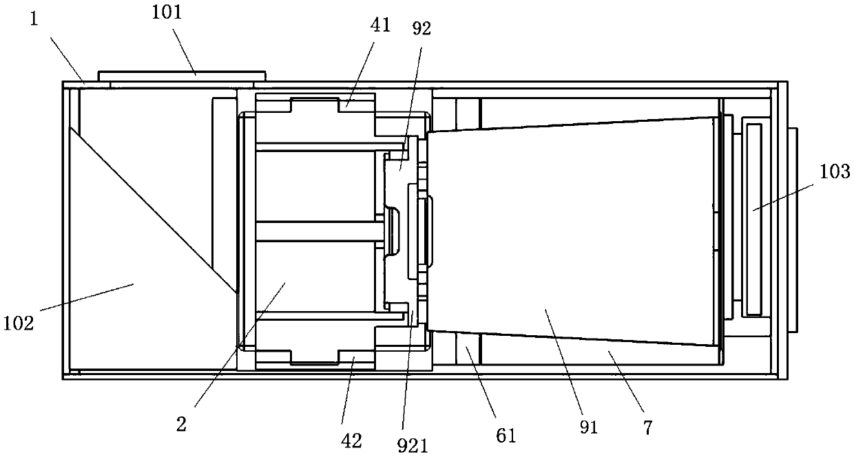
[0035] The base body 1 is used for installing the first lens 91 and the liquid lens 92 arranged along the optical axis and corresponding to each other. The seat body 1 includes an upper shell 11, a lower shell 12, a front shell 13 and a rear shell 14. The carrier 2, the drive assembly, the mounting frame 7, the reset member 8 and the gasket 6 are arranged on the upper shell 11, the lower shell The body 12, the front shell 13 and the rear shell 14 enclose the installation cavity.

[0036] The carrier 2 can move toward or away from the first lens 91 and is arranged in the seat body 1. When the carrier 2 moves, it can abut against the moving plate of the liquid lens 92 to drive the moving plate to move to The curvature of the liquid lens 92 is adjusted. In this embodiment, the br...

Embodiment 2

[0058] The periscope camera module of the present embodiment, such as Figure 1 to Figure 4 As shown, it includes the driving structure, the first lens 91 , the liquid lens 92 , the dustproof mirror 101 and the reflection mirror 102 in the first embodiment.

[0059] The first lens 91 and the liquid lens 92 are arranged in the housing 1 along the optical axis. In this embodiment, the liquid lens 92 is fixedly arranged on the first lens 91, that is, the first lens 91 is suspended in the base body 1 through the reset member 8 , and the carrier 2 , the first mover and the second mover are suspended in the base body 1 through the bracket 921 .

[0060] The dust-proof mirror 101 is arranged on the upper side wall of the base body 1 , and the light enters into the base body 1 through the dust-proof mirror 101 .

[0061] The reflector 102 is arranged in the seat body 1 corresponding to the dust-proof mirror 101, and is located on one side of the optical axis direction of the first le...


PUM


Abstract

The invention relates to the technical field of camera driving apparatuses, particularly relates to a driving structure and a periscope type camera module. The driving structure comprises a seat body,a bearing body, first stators and first rotors. The seat body is arranged for mounting a first lens and a liquid lens which are arranged along an optical axis and correspond to each other; the bearing body can be movably arranged inside the seat body in the mode of facing or getting away from the first lens, and the bearing body can abut against a moving plate of the liquid lens during moving todrive the moving plate to move so that the curvature of the liquid lens can be adjusted; the first stators are located on the left side and the right side of the bearing body in the optical axis direction and fixedly arranged inside the seat body; and the first promoters are located on the left side and the right side of the bearing body and fixedly arranged on the bearing body and correspond to the first stators, the first stators drive the first promoters to move, and the first promoter each comprise two first upper promoters located on the upper part of the bearing body and two first lowerpromoters located on the lower part of the bearing body. The driving structure has the advantages that the anti-shake effect is good and thickness is small.

Description

technical field [0001] The invention relates to the technical field of camera driving devices, in particular to a driving structure and a periscope camera module. Background technique [0002] The mobile phone camera is an important part of the mobile phone. Consumers have higher and higher requirements for the functions of the mobile phone camera such as auto focus and optical image stabilization when using the mobile phone. For the beauty and convenience of the mobile phone, the size of the mobile phone camera is also required to be smaller and smaller. . The liquid lens mainly changes the curvature of the interface of the liquid body by applying pressure to the chamber containing the liquid. The liquid lens can achieve ultra-close focusing without causing a decrease in optical resolution when performing optical anti-shake compensation , and light in weight, suitable for miniaturized imaging devices, therefore, more and more used in mobile phone cameras in recent years. ...

Claims


Application Information

Patent Timeline
IPC IPC(8): G02B7/09G03B5/00G03B13/36H02K41/035H04N5/225H04N5/232
CPCH02K41/0356G02B7/09G03B5/00G03B13/36H04N23/54H04N23/50H04N23/57H04N23/55H04N23/67H04N23/687
Inventor 王彬洪航庆刘志远
Owner DONGGUAN PRECISION PHOTONICS LTD
Why Eureka
Try Eureka