Blind pixel detection method and device

A detection method and blind element technology, applied in the field of image processing, can solve the problems of poor generalization and complex operation process, and achieve the effect of fast speed and accurate results.

Inactive Publication Date: 2019-04-05
NAVAL UNIV OF ENG PLA
View PDF6 Cites 10 Cited by
  • Summary
  • Abstract
  • Description
  • Claims
  • Application Information

AI Technical Summary

Problems solved by technology

[0004] 1. The calibration method needs to stop the system to take a single frame or a sequence of blackbody radiation images. The operation process is complicated and it is limited to the detection of fixed blind elements.
[0005] 2. The scene-based detection method can effectively detect random blind elements in the imaging process and is widely used, but this method is often aimed at a certain type or several types of images, and its generalization is poor

Method used


Image

  • Blind pixel detection method and device
  • Blind pixel detection method and device
  • Blind pixel detection method and device

Examples


Embodiment Construction

[0026] In order to make the purpose, technical solutions and advantages of the embodiments of the present invention clearer, the technical solutions in the embodiments of the present invention will be clearly and completely described below in conjunction with the drawings in the embodiments of the present invention. Obviously, the described embodiments It is a part of embodiments of the present invention, but not all embodiments. Based on the embodiments of the present invention, all other embodiments obtained by persons of ordinary skill in the art without creative efforts fall within the protection scope of the present invention.

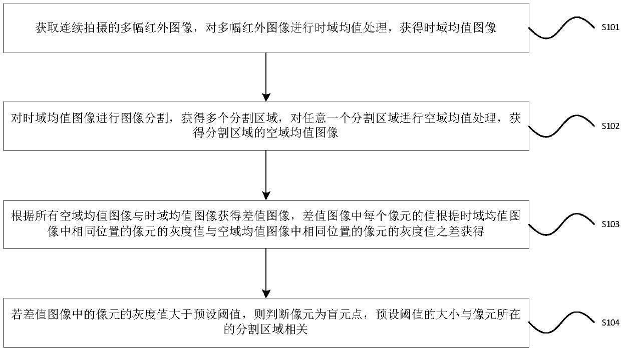
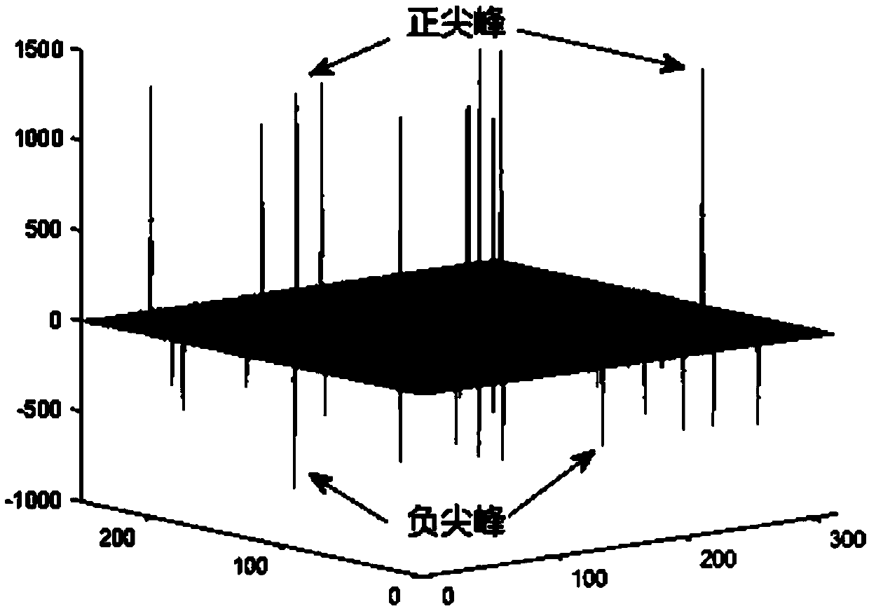
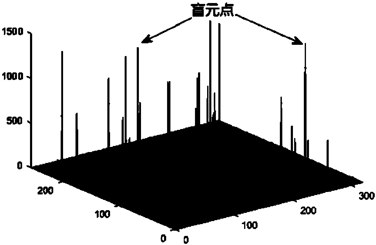
[0027] In order to overcome the above-mentioned problems in the prior art, an embodiment of the present invention provides a blind element detection method. A fixed value, and obviously different from the gray value of the adjacent area, it may be a blind pixel point. In the embodiment of the present invention, the time-domain average value is obt...


PUM


Abstract

The embodiment of the invention provides a blind pixel detection method and device, and the method comprises the steps: obtaining a plurality of continuously shot infrared images, carrying out the time domain mean value processing of the plurality of infrared images, and obtaining a time domain mean value image; Performing image segmentation on the time domain mean value image to obtain a plurality of segmentation regions, and performing spatial domain mean value processing on any one segmentation region to obtain a spatial domain mean value image of the segmentation region; Obtaining a difference image according to all the spatial domain mean value images and the time domain mean value image; If the value of the pixel in the difference image is greater than a preset threshold value, judging that the pixel is a blind pixel point; Wherein the size of the preset threshold value is related to the segmentation area where the pixel is located. The embodiment of the invention has the characteristics of high speed and accurate result. Practical application finds that the blind pixel detection method provided by the embodiment of the invention is particularly suitable for detecting the blind pixels in the infrared image of the ship.

Description

technical field [0001] The present invention relates to the field of image processing technology, and more specifically, to a blind element detection method and device. Background technique [0002] Due to the limitation of material defects and the influence of manufacturing process level in infrared imaging system, blind element problem will inevitably appear in the imaging process. Random blind cells are randomly generated when the imaging system is used, and the existence of blind cells will form brighter or darker points in the generated image, which will cause a high probability of missed detection and false alarms for small infrared target detection, etc. . Therefore, removing blind pixels is a key non-uniformity correction step in infrared imaging systems. [0003] At present, commonly used blind element detection algorithms are divided into two categories: calibration method and scene-based detection method: [0004] 1. The calibration method needs to stop the sys...

Claims


Application Information

Patent Timeline
Patent Type & Authority Applications(China)
IPC IPC(8): G06T7/00G06T7/11G06T7/136
CPCG06T7/0002G06T7/11G06T7/136G06T2207/10048
Inventor 王昕晔朱敏詹维马敬伟郭明李彪谢鑫黄璜黄桂
Owner NAVAL UNIV OF ENG PLA
Why Eureka
Try Eureka