Display panel and display device
A technology for display panels and display areas, applied in the manufacture of electrical components, electrical solid-state devices, semiconductor/solid-state devices, etc., can solve the problems of easy peeling of the encapsulation layer and barrier parts, reduce the possibility of cracks, improve the bonding force, The effect of ensuring package reliability
Active Publication Date: 2019-04-05
XIAMEN TIANMA MICRO ELECTRONICS
9 Cites 5 Cited by
AI-Extracted Technical Summary
Problems solved by technology
[0004] In view of this, an embodiment of the present invention provides a display panel and a display device ...
View moreMethod used
In the plane parallel to the base substrate 1, the adjacent third edges 23 of the adjacent two organic layers 20 are staggered from each other, and the adjacent fourth edges 24 of the adjacent two organic layers 20 are staggered from each other, The above-mentioned concave-convex structure 4 is also formed in the extending direction y of the blocking portion 2 . In the embodiment of the present invention, on the basis of forming the concave-convex structure 4 with the structure shown in FIG. Such an arrangement can not only further reduce the possibility of peeling between the encapsulation layer 3 and the barrier portion 2, but also improve the encapsulation reliability of the display panel. Moreover, in the embodiment of the present invention, the above-mentioned concave-convex structure 4 is also formed in the extending direction y of the barrier part 2, so that when the encapsulation layer 3 is subsequently formed, when the organic encapsulation layer in the encapsulation layer 3 is produced, the above-mentioned third edge 23 The concave-convex structure 4 formed staggered with the fourth edge 24 can drain the organic encapsulation layer along the y direction, so that the organic encapsulation layer in the encapsulation layer 3 can be confined between the barrier portion 2 and the display area AA, so as to avoid organic encapsulation. The layer extends outward beyond the barrier 2, thereby improving the packaging quality.
[0038] In the display panel provided by the embodiment of the present invention, the concave-convex structure 4 is provided on the surface of the barrier portion 2 in contact with the encapsulation layer 3, that is, the surface of the barrier portion 2 in contact with the encapsulation layer 3 is set as a non-flat surface, which is different from the existing Compared with the prior art, it is possible to increase the roughness of the surface of the barrier part 2 in contact with the encapsulation layer 3, so that when the display panel is bent, the concave-convex structure 4 can block possible occurrences between the encapsulation layer 3 and the barrier part 2. The relative displacement can improve the bonding force between the barrier part 2 and the encapsulation layer 3, and reduce the possibility of the encapsulation layer 3 peeling off from the barrier part 2 under the action of external force. Moreover, even if the relative displacement between the encapsulation layer 3 and the barrier part 2 under the action of external force causes cracks to appear, the existence of the above-mentioned concave-convex structure 4 can also prevent the cracks from continuing to extend, thereby reducing the gap between the barrier part 2 and the encapsulation layer. 3, the possibility of cracks that cause external water and oxygen to enter the display panel is generated to ensure the packaging reliability of the display panel.
[0046] Exemplarily, as shown in FIG. 7, FIG. 7 is a schematic top view of two adjacent organic layers in the blocking portion provided by the embodiment of the present invention, wherein the blocking portion 2 includes a bending axis 5; the blocking portion 2. The bending operation can be performed with the bending axis 5 as the axis. The projection of the organic layer 20 on the plane of the base substrate 1 includes a plurality of inflection points 200 . As shown in FIG. 7 , in the projection of two adjacent organic layers 20 on the plane where the substrate 1 is located, the angle θ1 between the line connecting two adjacent inflection points 200 and the bending axis 5 satisfies: 0≤θ1< 90°. Because the position of the inflection point 200 in the blocking part 2 receives a relatively large stress during bending, and the film layer at the position of the bending axis 5 receives a relatively large stress during bending, therefore, the embodiment of the present invention adopts Setting the connecting lines of multiple different positions with greater stress in the blocking portion 2 to be perpendicular to the bending axis 5 can improve the bending resistance of the blocking portion 2 when bending along the bending axis 5 to a certain extent. ability.
[0047] Optionally, the shape of the projection of the above-mentioned organic layer 20 forming the blocking portion 2 on the plane of the base substrate 1 can be any one or more of zigzag, wave, and fishbone, so as to pass The multi-layer organic layer 20 is stacked to form the above-mentioned concave-convex structure 4 on the surface in contact with the barrier part 2 and the encapsulation layer 3. On the basis of ensuring the encapsulation reliability of the display panel, the shape of the organic layer 20 can be adjusted according to the actual process conditions. Different selections are made so that the design of the display panel can be applied to a variety of different process conditi...
View moreAbstract
The embodiment of the invention provides a display panel and a display device, and relates to the technical field of display for solving the problem that in the prior art, a packaging layer and a blocking part are easy to peel off. The display panel comprises a substrate, a blocking part and a packaging layer, wherein the blocking part surrounds a display area of the display panel; and the blocking part is located on one side of the substrate; and the packaging layer is located on one side, away from the substrate, of the blocking part, wherein the surface of the blocking part in contact withthe packaging layer comprises a concave-convex structure.
Application Domain
Technology Topic
Image
Examples
- Experimental program(1)
Example Embodiment
[0031] In order to better understand the technical solutions of the present invention, the embodiments of the present invention will be described in detail below in conjunction with the accompanying drawings.
[0032] It should be clear that the described embodiments are only some of the embodiments of the present invention, not all of them. Based on the embodiments of the present invention, all other embodiments obtained by persons of ordinary skill in the art without creative efforts fall within the protection scope of the present invention.
[0033] Terms used in the embodiments of the present invention are only for the purpose of describing specific embodiments, and are not intended to limit the present invention. As used in the embodiments of the present invention and the appended claims, the singular forms "a", "said" and "the" are also intended to include the plural forms unless the context clearly indicates otherwise.
[0034] It should be understood that the term "and/or" used herein is only an association relationship describing associated objects, which means that there may be three relationships, for example, A and/or B, which may mean that A exists alone, and A and B exist simultaneously. B, there are three situations of B alone. In addition, the character "/" in this article generally indicates that the contextual objects are an "or" relationship.
[0035] It should be understood that although the terms first, second, third, etc. may be used to describe edges in the embodiments of the present invention, these edges should not be limited to these terms. These terms are only used to distinguish edges from one another. For example, without departing from the scope of the embodiments of the present invention, a first edge may also be called a second edge, and similarly, a second edge may also be called a first edge.
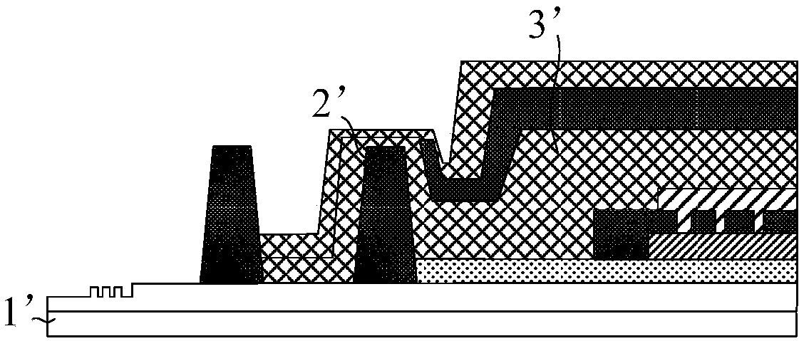
[0036] like figure 1 as shown, figure 1 It is a schematic cross-sectional view of a frame area of a display panel in the prior art, wherein the display panel includes a barrier part 2' disposed on a base substrate 1', and the barrier part 2' is in direct contact with the encapsulation layer 3'. However, the display panel with this structure is prone to the problem of encapsulation failure. The inventors have found through research that since the contact surface between the barrier part 2' and the encapsulation layer 3' is too smooth, after the display panel is bent, the barrier part 2' and the encapsulation layer 3' are prone to peeling off at the interface position , the space formed after the two are peeled off may provide a channel for external water and oxygen to enter, which will cause the problem of package failure.
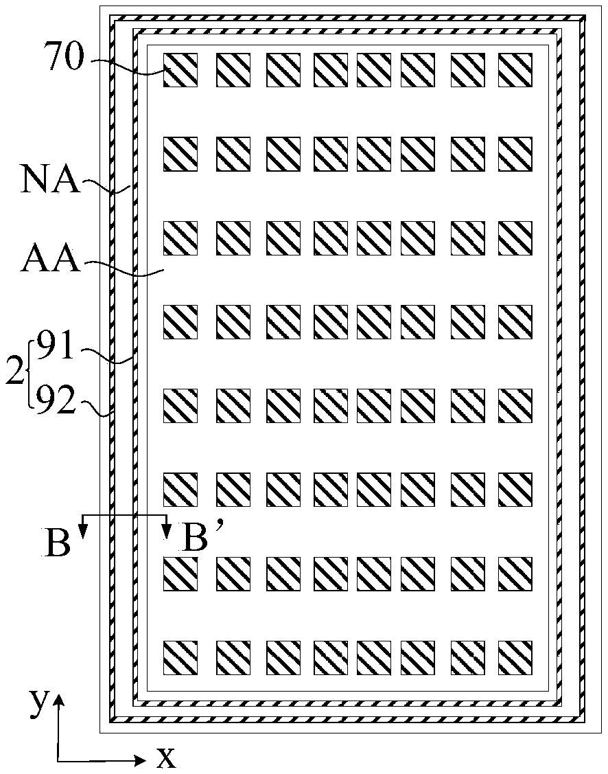
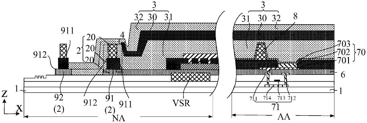
[0037] In view of this, an embodiment of the present invention provides a display panel, such as figure 2 and image 3 as shown, figure 2 It is a schematic top view of a display panel provided by an embodiment of the present invention, image 3 for figure 2 A schematic cross-sectional view along BB', wherein the direction x and the direction y are located in the plane where the display panel is located, and the direction z is perpendicular to the plane where the display panel is located. Specifically, the display panel includes: a base substrate 1 , a blocking portion 2 and an encapsulation layer 3 . like figure 1 As shown, the blocking portion 2 surrounds the display area AA of the display panel. like figure 2 As shown, the barrier part 2 is located on one side of the base substrate 1; the encapsulation layer 3 is located on the side of the barrier part 2 away from the base substrate 1;
[0038] In the display panel provided by the embodiment of the present invention, the concave-convex structure 4 is provided on the surface of the barrier part 2 in contact with the encapsulation layer 3, that is, the surface of the barrier part 2 in contact with the encapsulation layer 3 is set as a non-flat surface, which is different from the prior art. ratio, the roughness of the surface of the blocking portion 2 in contact with the encapsulation layer 3 can be increased, so that when the display panel is bent, the concave-convex structure 4 can block the relative displacement that may occur between the encapsulation layer 3 and the blocking portion 2 , so that the bonding force between the barrier part 2 and the encapsulation layer 3 can be improved, and the possibility of the encapsulation layer 3 peeling off from the barrier part 2 under the action of external force can be reduced. Moreover, even if the relative displacement between the encapsulation layer 3 and the barrier part 2 under the action of external force causes cracks to appear, the existence of the above-mentioned concave-convex structure 4 can also prevent the cracks from continuing to extend, thereby reducing the gap between the barrier part 2 and the encapsulation layer. 3, the possibility of cracks that cause external water and oxygen to enter the display panel is generated to ensure the packaging reliability of the display panel.
[0039] Exemplary, such as image 3 and Figure 4 as shown, Figure 4 It is a three-dimensional schematic diagram of a part of the blocking part located on the left frame of the display panel, wherein the above-mentioned blocking part 2 includes at least two layers of organic layers 20 stacked; the edges of adjacent two layers of organic layers 20 are staggered from each other so that The surface of the barrier part 2 formed by stacking at least two organic layers 20 in contact with the encapsulation layer 3 can form the above-mentioned concave-convex structure 4, and then the relative displacement between the encapsulation layer 3 and the barrier part 2 can be prevented by the concave-convex structure 4 , improving the packaging reliability of the display panel.
[0040] It should be noted that, in the accompanying drawings of this application document, the embodiment of the present invention is described by taking the blocking part 2 including three organic layers 20 as an example, but those skilled in the art can understand that the blocking part 2 is also It can be formed by two or more than three organic layers 20, as long as the edges of two adjacent organic layers 20 are staggered to form the above-mentioned concave-convex structure 4, which is not limited in the embodiment of the present invention.
[0041] like figure 2 and Figure 4shown, wherein the blocking part 2 located at the left border of the display panel extends along the y-direction, the blocking part 2 includes a first edge 21 and a second edge 22 arranged oppositely, and the first edge 21 and the second edge 22 are along the direction x is arranged, and the direction x is perpendicular to the extension direction y of the blocking portion 2 at this position. The first edge 21 is close to the display area AA, and the second edge 22 is far away from the display area AA.
[0042] Wherein, in a plane parallel to the base substrate 1, the adjacent first edges 21 of the two adjacent organic layers 20 are staggered from each other, and the adjacent second edges 22 of the two adjacent organic layers 20 are staggered from each other, so as to The concave-convex structure 4 is formed on the side of the barrier portion 2 close to the display area AA and the side of the barrier portion 2 away from the display area AA, so that the barrier portion 2 is close to the surface of the display area AA in contact with the encapsulation layer 3 and away from the display area AA. The surface of the area AA in contact with the encapsulation layer 3 is not easily peeled off from the encapsulation layer 3, which further ensures the encapsulation reliability of the display panel.
[0043] It should be understood that in Figure 4 The structure of the blocking portion 2 is only described by taking the blocking portion 2 located at the left border of the display panel as an example. figure 2 As shown, the blocking portion 2 is a ring-shaped structure surrounding the display area AA of the display panel. Therefore, at the upper and lower borders of the display panel, the blocking portion 2 can extend along the direction x. The first edge 21 and the second edge 22 of the organic layer 20 may be staggered along the y-direction, and the specific structure thereof is the same as that of the Figure 4 The structures shown are similar, and details are not described herein again in this embodiment of the present invention.
[0044] Exemplary as Figure 5 and Image 6 shown, Figure 5 is another three-dimensional schematic diagram of a part of the blocking portion located on the left frame of the display panel; Image 6 Yes Figure 5 A schematic cross-sectional view along CC', wherein the blocking part 2 further includes a third edge 23 and a fourth edge 24 arranged opposite to each other, and the third edge 23 and the fourth edge 24 are arranged along the extending direction y of the blocking part 2.
[0045] In a plane parallel to the base substrate 1, the adjacent third edges 23 of two adjacent organic layers 20 are staggered from each other, and the adjacent fourth edges 24 of two adjacent organic layers 20 are staggered from each other, so as to prevent The aforementioned concave-convex structure 4 is also formed in the extending direction y of the portion 2 . The embodiments of the present invention are formed such as Figure 4 On the basis of the concave-convex structure 4 of the shown structure, the third edge 23 and the fourth edge 24 arranged along the extension direction y in the blocking portion 2 can also be staggered to form the concave-convex structure 4, which can not only further reduce the encapsulation layer 3 The possibility of peeling off from the blocking portion 2 improves the packaging reliability of the display panel. Moreover, in the embodiment of the present invention, the above-mentioned concave-convex structure 4 is also formed in the extending direction y of the blocking portion 2, so that when the encapsulation layer 3 is subsequently formed, when the organic encapsulation layer in the encapsulation layer 3 is fabricated, the above-mentioned third edge 23 The concave-convex structure 4 formed by being staggered from the fourth edge 24 can drain the organic encapsulation layer along the y direction, so that the organic encapsulation layer in the encapsulation layer 3 can be restricted between the blocking portion 2 and the display area AA to avoid organic encapsulation. The layers extend outward beyond the blocking portion 2, thereby improving the packaging quality.
[0046] Exemplary as Figure 7 shown, Figure 7 It is a schematic top view of two adjacent organic layers in the blocking part provided in the embodiment of the present invention, wherein the blocking part 2 includes a bending axis 5; the blocking part 2 can be bent with the bending axis 5 as the axis. The projection of the organic layer 20 on the plane where the base substrate 1 is located includes a plurality of inflection points 200 . like Figure 7 As shown, in the projection of the two adjacent organic layers 20 on the plane where the base substrate 1 is located, the angle θ1 between the line connecting the two adjacent inflection points 200 and the bending axis 5 satisfies: 0≤θ1<90°. Because the position of the inflection point 200 in the blocking portion 2 is subjected to greater stress during bending, and the film layer at the position of the bending axis 5 is also subjected to greater stress during bending, therefore, in the embodiment of the present invention, the By setting the connecting lines of a plurality of different positions in the blocking part 2 with greater stress to the bending axis 5 to be perpendicular to the bending axis 5 , the bending resistance of the blocking part 2 when it is bent along the bending axis 5 can be improved to a certain extent. ability.
[0047] Optionally, the projected shape of the organic layer 20 constituting the barrier portion 2 on the plane where the base substrate 1 is located can be any one or more of zigzag, wavy, and fishbone shapes, so that through the multilayer organic The stacking of the layers 20 forms the above-mentioned concave-convex structure 4 on the surface of the barrier portion 2 in contact with the encapsulation layer 3. On the basis of ensuring the encapsulation reliability of the display panel, the shape of the organic layer 20 can be varied according to the actual process conditions. It is selected so that the design of the display panel can be applied to a variety of different process conditions, which improves the flexibility of the manufacturing process of the barrier portion 2 .
[0048] For example, as Figure 8 shown, Figure 8 It is another schematic top view of two adjacent organic layers in the barrier portion provided by the embodiment of the present invention, wherein, in the embodiment of the present invention, the shape of the projection of the adjacent two organic layers 20 on the plane where the base substrate 1 is located is set. are the same, and the projected areas of the two on the plane where the base substrate 1 is located are set to be different, so that the surface of the formed barrier portion 2 in contact with the encapsulation layer 3 can form the above-mentioned concave-convex structure, and in the actual process, you can choose The above-mentioned two adjacent organic layers 20 are respectively vapor-deposited on two masks with the same shape and different areas.
[0049] or, as in Figure 9 shown, Figure 9 This is another schematic top view of two adjacent organic layers in the barrier portion provided by the embodiment of the present invention. The embodiment of the present invention can also make the shape and area of the projection of the two adjacent organic layers 20 on the plane where the base substrate 1 is located. are the same, specifically, such as Figure 9 As shown, the projections of two adjacent organic layers 20 with the same shape and area on the plane where the base substrate 1 is located can be set to overlap, and the projections of the two adjacent organic layers 20 on the plane where the base substrate 1 is located can be set to overlap. The surfaces of the barrier portion 2 and the encapsulation layer 3 which are formed after being stacked in such a manner that they are staggered and in contact with each other also include the aforementioned concave-convex structure. In addition, in the embodiment of the present invention, the shapes and areas of two adjacent organic layers 20 in the barrier portion 2 are set to be the same. In actual processes, masks of the same shape can be used to form each organic layer in the barrier portion 2 . 20. When fabricating the organic layers 20 of different layers, the mask plate only needs to be translated by a corresponding distance, which is beneficial to reduce the process cost.
[0050] or, as in Figure 10 shown, Figure 10 This is another schematic top view of two adjacent organic layers in the blocking portion provided by the embodiment of the present invention. In the embodiment of the present invention, the projection shapes of the adjacent two organic layers 20 on the plane where the base substrate 1 is located can also be different. In this way, the surface of the stacked barrier portion 2 in contact with the encapsulation layer 3 can also be formed with the aforementioned concavo-convex structure. Under this condition, in the embodiment of the present invention, any two masks with different shapes can be used to form the above-mentioned two adjacent organic layers 20 by vapor deposition, so that the barrier portion 2 formed by the stacked organic layers 20 is connected to the package. The above-mentioned concave-convex structure is formed on the surface contacted by the layer 3 , which improves the process flexibility during the preparation of the barrier portion 2 .
[0051] like image 3 As shown, the blocking portion 2 is located in the non-display area NA of the display panel. The display area AA includes a layered planarization layer 6 , a pixel definition layer 7 and a support column 8 . The planarization layer 6 is close to the base substrate 1 , the support pillars 8 are far away from the base substrate 1 , and the pixel definition layer 7 is located between the planarization layer 6 and the support pillars 8 . like figure 2 and image 3 As shown, the display area AA further includes a plurality of sub-pixels 70 , wherein the position of each sub-pixel 70 is defined by the above-mentioned pixel definition layer 7 . Each sub-pixel 70 includes an anode 701 , a light-emitting layer 702 and a cathode 703 which are arranged in layers. The support column 8 is used to support the mask used in the evaporation process when a film layer such as the light-emitting layer 702 of the sub-pixel 70 is formed by the evaporation process.
[0052] Exemplary as image 3 As shown, the display area AA of the display panel further includes a thin film transistor 71 for driving the sub-pixel 70 to work, wherein the thin film transistor 71 includes a source electrode 711 , a drain electrode 712 , a gate electrode 713 and an active layer 714 .
[0053] continue to refer to image 3 , the above-mentioned blocking part 2 includes three layers of organic layers 20 arranged in layers; the organic layer 20 close to the base substrate 1 is arranged in the same layer as the planarization layer 6, and the organic layer 20 in the middle is arranged in the same layer as the pixel definition layer 7, away from the substrate The organic layer 20 of the base substrate 1 is disposed in the same layer as the support pillars 8 . In this way, during fabrication, the blocking portion 2 can be fabricated in the same layer as the aforementioned planarization layer 6 , the pixel definition layer 7 and the support pillar 8 to simplify the fabrication process.
[0054] Exemplary as Figure 11 , Figure 12 and Figure 13 shown, Figure 11 It is another three-dimensional schematic diagram of a part of the blocking part located on the left border of the display panel, Figure 12 Yes Figure 11 A top-view schematic diagram of , Figure 13 Yes Figure 11 A schematic cross-sectional view along DD', wherein the projection of the organic layer 20 close to the base substrate 1 on the plane of the base substrate 1 is the first projection 201; the projection of the organic layer 20 in the middle on the plane of the base substrate 1 is the second projection 202 ; the projection of the organic layer 20 away from the base substrate 1 on the plane where the base substrate 1 is located is the third projection 203 . In the embodiment of the present invention, the areas of the first projection 201 and the third projection 203 are larger than the area of the second projection 202 ; and the first projection 201 covers the second projection 202 ; That is to say, the edge of the organic layer 20 close to the base substrate 1 and the edge of the organic layer 20 away from the base substrate are staggered in the same direction with respect to the edge of the organic layer 20 located in the middle, for example, in Figure 13 In the embodiment shown, the edge of the organic layer 20 close to the base substrate 1 and the edge of the organic layer 20 away from the base substrate are both directed away from the edge of the organic layer 20 located in the center relative to the edge of the organic layer 20 located in the center. The direction of the center of the three layers is staggered, so that the size of the organic layer 20 in the middle can be minimized, and the size of the organic layers 20 in the upper and lower layers is larger, so that the edges of the three organic layers 20 are staggered to form a more obvious concave-convex structure. If the dimensions of the three inorganic layers 20 constituting the barrier portion 2 are designed to gradually increase or decrease along the z-direction, when the dimensions of the two adjacent organic layers 20 are similar, there may be a possibility that two adjacent organic layers 20 may have similar dimensions. The distance between the edges of the layer 20 is too close to form a smooth transition, so that the concave-convex mechanism cannot be formed on the surface of the blocking portion 2 .
[0055] Based on this, the embodiment of the present invention also provides a design method, such as Figure 14 , Figure 15 and Figure 16 shown, Figure 14 It is another three-dimensional schematic diagram of a part of the blocking part located on the left border of the display panel, Figure 15 Yes Figure 14 A top-view schematic diagram of , Figure 16 Yes Figure 14 A schematic cross-sectional view along EE', the embodiment of the present invention can also make the area of the second projection 202 larger than the areas of the first projection 201 and the third projection 203; and make the second projection 202 cover the first projection 201; the second projection 202 covers the third projection 203, that is to say, the edge of the organic layer 20 close to the base substrate 1 and the edge of the organic layer 20 far from the base substrate are both close to the edge of the organic layer 20 located in the center relative to the edge of the organic layer 20 located in the center. The directions of the centers of the organic layers 20 are staggered, so that the edges of the three-layer organic layers 20 are staggered to form a more obvious concave-convex structure.
[0056] optional, as in Figure 12As shown, the shortest distance between the edge of the second projection 202 and the edge of the first projection 201 is the first distance d1, and the shortest distance between the edge of the second projection 202 at the same position and the edge of the third projection 203 is the second distance d2; the first distance d1 is equal to the second distance d2. That is, the edge of the organic layer 20 close to the base substrate 1 and the edge of the organic layer 20 away from the base substrate are staggered by the same distance with respect to the edge of the organic layer 20 located in the middle, that is, the edge of the organic layer 20 will be close to the substrate. The shape and area of the organic layer 20 of the substrate 1 are set to be the same as the shape and area of the organic layer 20 far away from the base substrate, so that when the blocking portion 2 is fabricated, the same mask can be used to fabricate the above-mentioned close to the base substrate 1 respectively. The organic layer 20 and the organic layer 20 away from the base substrate to reduce the process cost. Of course, if Figure 15 As shown, in the embodiment of the present invention, the above-mentioned first distance d1 and second distance d2 can also be different, so that a concave-convex structure can also be formed on the surface of the blocking portion 2 .
[0057] Exemplary as figure 2 and image 3 As shown, the above-mentioned blocking part 2 includes a first blocking part 91 and a second blocking part 92; the first blocking part 91 and the second blocking part 92 are located on the same side of the base substrate 1; and the first blocking part 91 surrounds the display panel In the display area AA, the second barrier portion 92 surrounds the first barrier portion 91; the encapsulation layer 3 includes the first inorganic layer 31, the organic encapsulation layer 30 and the second inorganic layer 32 which are stacked in layers; the first inorganic layer and the first barrier portion 91 and the second blocking part 92 are in contact; the organic encapsulation layer 30 covers the display area AA, and the edge of the organic encapsulation layer 30 is in contact with the edge of the first blocking part 91 close to the display area AA. In the embodiment of the present invention, the arrangement of the first blocking portion 91 can prevent the organic encapsulation layer 30 from crossing the first blocking portion 91, so that the organic encapsulation layer 30 can avoid contact with water and oxygen in the external environment, thereby ensuring the reliability of the encapsulation of the display panel. sex.
[0058] Exemplary as image 3 As shown, the first inorganic layer 31 and the second inorganic layer 32 in the encapsulation layer 3 described above may be located between the first barrier portion 91 and the second barrier portion 92 . The above-mentioned first blocking portion 91 and second blocking portion 92 both include a first side surface 911 and a second side surface 912 arranged oppositely, and the plane where the first side surface 911 and the second side surface 912 are located intersects with the plane where the base substrate 1 is located; Close to the display area AA, and the second side is far away from the display area AA; such as image 3 As shown, both the first side surface 911 and the second side surface 912 of the first blocking portion 91 include the concave-convex structure 4 , and the first side surface 911 of the second blocking portion 92 includes the concave-convex structure 4 , so that the blocking portion is in contact with the encapsulation layer 3 . Each surface of the display panel is not easily peeled off from the encapsulation layer 3, which further ensures the encapsulation reliability of the display panel.
[0059] Exemplarily, during the preparation of the first inorganic layer 31 and the second inorganic layer 32 , the first inorganic layer 31 and/or the second inorganic layer 32 may diffuse to the side of the second barrier portion 92 away from the display area AA. phenomenon, that is, as Figure 17 shown, Figure 17 Yes figure 2 Another schematic cross-sectional view along BB', in this case, the side of the second blocking portion 92 away from the display area AA also includes the encapsulation layer 3; correspondingly, the embodiment of the present invention can also make the second blocking portion 92 The second side surface 912 also includes a concave-convex structure, so that when the phenomenon of diffusion of the first inorganic layer 31 and the second inorganic layer 32 occurs, the bonding force between the second side surface 912 of the second barrier portion 92 and the encapsulation layer 3 can be improved. .
[0060] Embodiments of the present invention also provide a display device, such as Figure 18 shown, Figure 18 It is a schematic structural diagram of a display device provided by an embodiment of the present invention, wherein the display device includes the above-mentioned display panel 100 . The specific structure of the display panel 100 has been described in detail in the above-mentioned embodiments, and will not be repeated here. certainly, Figure 18 The shown display device is only for illustration, and the display device may be any electronic device with display function, such as a mobile phone, a tablet computer, a notebook computer, an electronic paper book, or a television.
[0061] In the display device provided by the embodiment of the present invention, by providing a concave-convex structure on the surface of the blocking portion in contact with the encapsulation layer, that is, setting the surface of the blocking portion in contact with the encapsulation layer as a non-flat surface, compared with the prior art, the size of the display device can be increased. The roughness of the surface of the barrier portion in contact with the encapsulation layer, so that when the display device is bent, the concave-convex structure can block the relative displacement that may occur between the encapsulation layer and the barrier portion, thereby improving the relationship between the barrier portion and the encapsulation layer. The bonding force between them reduces the possibility that the encapsulation layer is peeled off from the barrier part under the action of external force. In addition, even if the relative displacement between the encapsulation layer and the blocking part under the action of external force causes the occurrence of cracks, the existence of the concave-convex structure can prevent the continuous extension of the cracks, thereby reducing the occurrence of cracks between the blocking part and the encapsulation layer. The possibility of outside water and oxygen entering the crack of the display panel ensures the packaging reliability of the display device.
[0062] The above descriptions are only preferred embodiments of the present invention, and are not intended to limit the present invention. Any modifications, equivalent replacements, improvements, etc. made within the spirit and principles of the present invention shall be included in the present invention. within the scope of protection.
Login to view more PUM


Description & Claims & Application Information
We can also present the details of the Description, Claims and Application information to help users get a comprehensive understanding of the technical details of the patent, such as background art, summary of invention, brief description of drawings, description of embodiments, and other original content. On the other hand, users can also determine the specific scope of protection of the technology through the list of claims; as well as understand the changes in the life cycle of the technology with the presentation of the patent timeline. Login to view more.
Login to view more Similar technology patents
Method for preparing good-stability super-hydrophobic fabrics
Owner:LANZHOU INST OF CHEM PHYSICS CHINESE ACAD OF SCI
Preparation method of efficient increased-transmission and antireflection glass
Owner:(CNBM) BENGBU DESIGN & RES INST FOR GLASS IND CO LTD +1
Preparation method and application of polyolefin/nanocrystal cellulose composite diaphragm
InactiveCN105185940AImprove hydrophilicityImprove bindingCell seperators/membranes/diaphragms/spacersPorous membraneChemistry
Owner:XUCHENG FUJIAN SCI & TECH
High-temperature resistant aluminum powder paint
Owner:QINGDAO CREEK NEW ENVIRONMENTAL PROTECTION MATERIAL
Weak target detecting and tracking method in infrared image sequence
InactiveCN1606033AEasy to handleImprove bindingCharacter and pattern recognitionDiffusion functionDetection performance
Owner:SHANGHAI JIAO TONG UNIV
Classification and recommendation of technical efficacy words
- Improve binding
- Reduced likelihood of cracks
Fc variants with altered binding to FcRn
Owner:XENCOR
Compositions and methods of use of targeting peptides for diagnosis and therapy
InactiveUS20050191294A1Improve concentrationImprove bindingPeptide/protein ingredientsAntibody mimetics/scaffoldsTarget peptideBone cancer
Owner:BOARD OF RGT THE UNIV OF TEXAS SYST
Methods for discovering ligands
InactiveUS6080585ABig advantageImprove bindingSequential/parallel process reactionsSugar derivativesOligonucleotideRNA molecule
Owner:OXFORD GENE TECH
Cation modified dyeing method of ceiba fiber textiles
Owner:SHANGHAI UNIV OF ENG SCI
Ceramic diaphragm for lithium ion battery and preparation method of ceramic diaphragm
InactiveCN105514328AImproved cycle life and rate performanceImprove bindingCell component detailsSolventCeramic particle
Owner:TIANNENG SAFT ENERGY JOINT CO
Anti-corrosion reinforcing structure for column
Owner:舟山市宏达交通工程有限责任公司
Molding heat treatment method for standard duplex steel elbow
ActiveCN110835669AReduced likelihood of cracksImprove pass rateFurnace typesHeat treatment furnacesStructural engineeringDual-phase steel
Owner:SINOPEC ENG +1
High-strength hot-dip galvanized steel sheet having excellent surface quality and resistance spot weldability, and method for manufacturing same
PendingCN114867886AReduced likelihood of cracksReduce liquid metal embrittlementHot-dipping/immersion processesFurnace typesSteel platesGalvanization
Owner:POSCO
Touch screen, display device and preparation method of touch screen
PendingCN113419641AImprove ductilityReduced likelihood of cracksSolid-state devicesSemiconductor/solid-state device manufacturingPhysicsTouch panel
Owner:BOE TECH GRP CO LTD +1