Optical module

A technology of optical modules and reflected light, applied in the field of optical modules, can solve the problems of reducing package size, increasing the volume of optical modules, disadvantages, etc.

Inactive Publication Date: 2019-04-05
HISENSE BROADBAND MULTIMEDIA TECH
View PDF5 Cites 3 Cited by
  • Summary
  • Abstract
  • Description
  • Claims
  • Application Information

AI Technical Summary

Problems solved by technology

[0004] However, the use of four lasers in existing optical modules with integrated OTDR functi...

Method used


Image

  • Optical module
  • Optical module
  • Optical module

Examples


Embodiment Construction

[0015] Reference will now be made in detail to the exemplary embodiments, examples of which are illustrated in the accompanying drawings. When the following description refers to the accompanying drawings, the same numerals in different drawings refer to the same or similar elements unless otherwise indicated. The implementations described in the following exemplary examples do not represent all implementations consistent with the present invention. Rather, they are merely examples of apparatuses and methods consistent with aspects of the invention as recited in the appended claims.

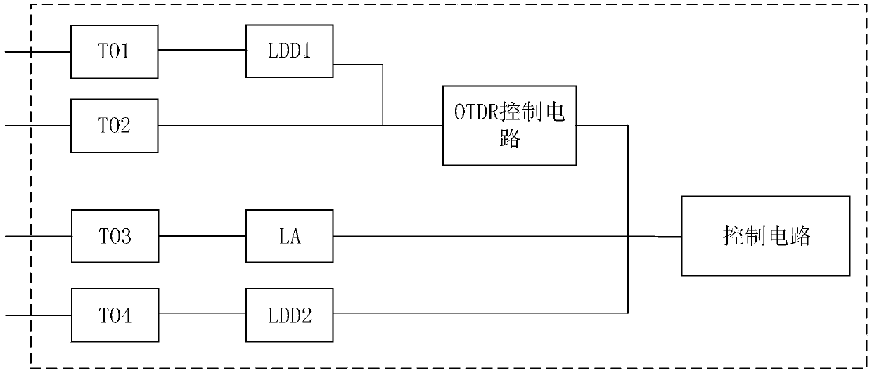
[0016] see figure 1 , after the existing optical module integrates the OTDR function, two groups of laser devices will be set up, each group of laser devices includes a laser transmitter and a laser receiver, that is, laser transmitter TO1 and laser receiver TO2, as well as laser transmitter TO4 and laser receiver Laser receiver TO3.

[0017] The laser receiver TO3 and the laser transmitter TO...


PUM


Abstract

The invention discloses an optical module. The optical module comprises a circuit board, a laser emitter and a first laser receiver. The surface of the circuit board is provided with a golden finger,a control chip, a first driving chip and a second driving chip. The first driving chip and the emission pin of the golden finger are connected. The second driving chip and the control chip are connected. The first driving chip and the second driving chip drive the laser emitter in a time-sharing manner to generate the laser of a first wavelength. The laser enters into an external optical fiber. The emission pin provides emission data to the first driving chip. The first laser receiver receives the reflected light of the first wavelength from the external optical fiber. The first driving chip and the second driving chip share the laser emitter so that an optical module function and an effect that the laser emitters emit light in the function can be realized; and one laser can be saved, which is good for reducing the size of the optical module and decreasing the packaging size of the optical module.

Description

technical field [0001] The invention relates to the technical field of optical fiber communication, in particular to an optical module. Background technique [0002] In the optical communication industry, optical time domain reflectometer (Optical Time Domain Reflectometer, OTDR) equipment is usually used to analyze whether there are faults such as breakpoints in optical fiber links. OTDR equipment inputs a series of optical bursts to the optical fiber, and the optical bursts will be reflected back when they encounter media with different refractive indices. Then, the reflected optical signal is received on the same side as the input optical burst, and the intensity of the optical signal (as a function of time) can be detected, and then converted into the length of the optical fiber according to the intensity of the optical signal. [0003] In order to avoid carrying OTDR equipment on site to analyze the breakpoint position of the optical fiber link, the existing optical mo...

Claims


Application Information

Patent Timeline
IPC IPC(8): H04B10/071H04B10/40G01M11/00
CPCG01M11/3109H04B10/071H04B10/40
Inventor 吴铁山
Owner HISENSE BROADBAND MULTIMEDIA TECH
Why Eureka
Try Eureka