Rotating mounter head mechanism

A technology of patch head and rotary head, applied in the direction of electrical components, electrical components, etc., can solve the problems of uneven pick-up and placement movement of the patch head, low pickup or placement accuracy, etc., to achieve smooth pickup and placement. Mounting efficiency, easy repair and replacement effect

Inactive Publication Date: 2019-04-05
CETC BEIJING ELECTRONICS EQUIP
View PDF4 Cites 1 Cited by
  • Summary
  • Abstract
  • Description
  • Claims
  • Application Information

AI Technical Summary

Problems solved by technology

[0003] In view of this, the present invention provides a rotary placement head mechanism, which is used to solve the problem that the pick-up and placement movement of the placement head is not stable, and the pick-up or placement accuracy is low during pick-up or placement.

Method used


Image

  • Rotating mounter head mechanism
  • Rotating mounter head mechanism
  • Rotating mounter head mechanism

Examples


Embodiment Construction

[0031] In order to make the purpose, technical solutions and advantages of the embodiments of the present invention more clear, the following will clearly and completely describe the technical solutions of the embodiments of the present invention in conjunction with the drawings of the embodiments of the present invention. Apparently, the described embodiments are some, not all, embodiments of the present invention. All other embodiments obtained by those skilled in the art based on the described embodiments of the present invention fall within the protection scope of the present invention.

[0032] The rotary patch head mechanism according to the embodiment of the present invention will be described in detail below with reference to the accompanying drawings.

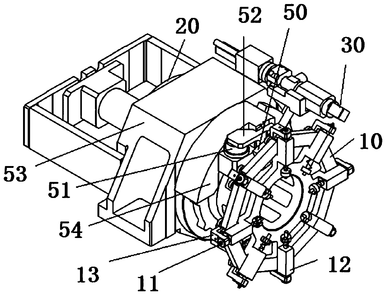
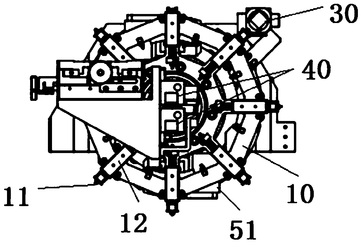
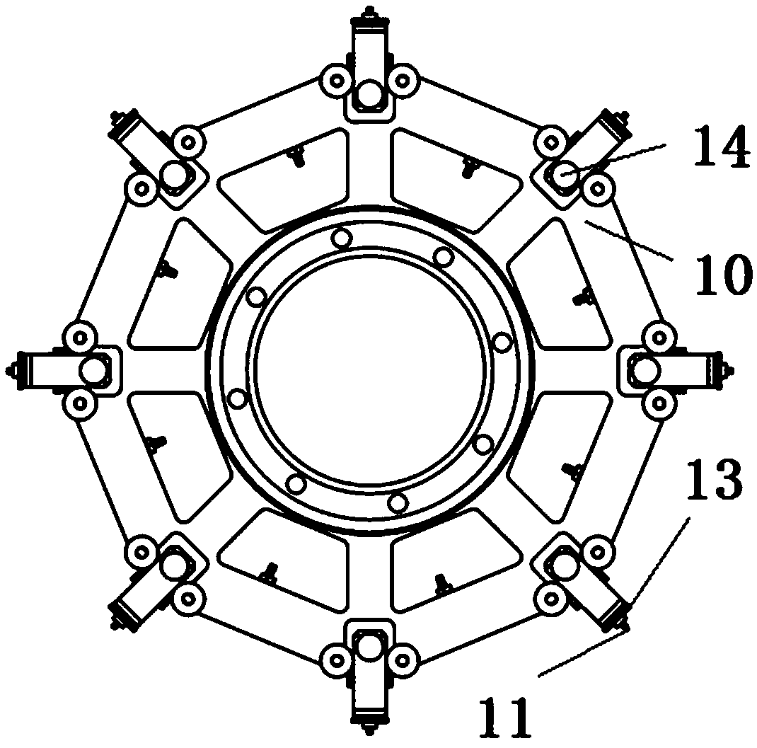
[0033] like Figure 1 to Figure 4 As shown, the rotary patch head mechanism according to the embodiment of the present invention includes a rotary head 10 , a driving motor 20 , a first recognition camera 30 , a secon...


PUM


Abstract

The invention provides a rotating mounter head mechanism. The mechanism comprises a rotating head, a drive motor, a first identification camera, a second identification camera, a jacking structure anda buffer plate, wherein the rotating head is provided with a plurality of telescopic movable suction nozzles; the drive motor is connected to the rotary head and is capable of driving the rotating head to rotate; the first identification camera is used for acquiring a first image of a wafer chip of each of the suction nozzles; the first image is used for acquiring first position information of the wafer chip; the second identification camera is used for acquiring a second image of a to-be-mounted position of the wafer chip on a work platform; the second image is used for acquiring the secondposition information of the to-be-mounted position; the jacking structure is disposed adjacent to the rotating head and is capable of driving the nozzles to telescopically move; the buffer plate and the jacking structure are connected; the buffer plate can stop against the nozzles when the nozzles are rotated to the corresponding position of the jacking structure; and the jacking structure can drive the buffer plate to drive the nozzles to telescopically move. With the rotating mounter head mechanism provided by the invention, the instability of the jacking structure can be avoided when the nozzles are lifted by the jacking structure so that the picking and mounting movement is smooth, and the picking or mounting precision is guaranteed.

Description

technical field [0001] The invention relates to the technical field of electronic placement, in particular to a rotary placement head mechanism. Background technique [0002] Under the development trend of thinner and lighter electronic products, Surface Mounted Technology (SMT) has rapidly developed into the mainstream technology and process in the current electronic industry. The placement machine is the most critical automation equipment in the SMT production line, and its placement efficiency and accuracy directly determine the production efficiency and accuracy of the SMT production line. At present, the vertical rotary SMT head mechanism includes four small motors that control the Z-axis movement, and a direct-drive rotary (DDR) motor that is responsible for the rotation of the SMT head. When the SMT head is in place, it picks up and mounts. Such a SMT head The mechanism is large in size, and once a problem occurs, it will take a long time to repair and replace, and i...

Claims


Application Information

Patent Timeline
Patent Type & Authority Applications(China)
IPC IPC(8): H05K13/04H05K13/08
CPCH05K13/0408H05K13/08
Inventor 袁晓春高泽周丹王军帅霍杰崔洁郎平
Owner CETC BEIJING ELECTRONICS EQUIP
Why Eureka
Try Eureka