Treating liquid recycling device for tail gas treatment

A recovery device and tail gas treatment technology, applied in the direction of using liquid separation agent, feeding/discharging device of sedimentation tank, sedimentation tank, etc., can solve the problem that the treatment liquid cannot be recycled and reused, the treatment liquid cannot be separated, and the treatment liquid is lost. Fast and other problems, to achieve good flocculation effect, reduce the difficulty of treatment, and achieve the effect of recycling and recycling

Inactive Publication Date: 2019-04-09
界首市宜民电子科技有限公司
View PDF2 Cites 0 Cited by
  • Summary
  • Abstract
  • Description
  • Claims
  • Application Information

AI Technical Summary

Problems solved by technology

[0004] In some existing tail gas treatment devices, when the gas is discharged, the treatment liquid cannot be effectively separated from the gas, resulting in too fast loss of the treatment liquid, increasing the cost, and the treatment liquid cannot be recycled and reused

Method used


Image

  • Treating liquid recycling device for tail gas treatment
  • Treating liquid recycling device for tail gas treatment

Examples


Embodiment 1

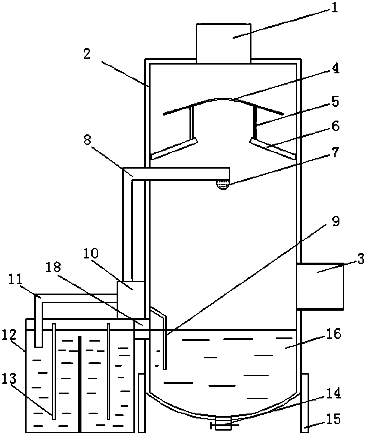
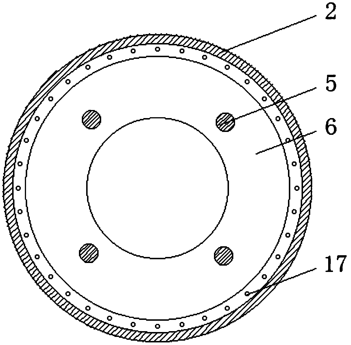
[0030] Embodiment 1, a treatment liquid recovery device for tail gas treatment, comprising a treatment tank 2, an air intake pipe 3 and an exhaust pipe 1, the upper end of the treatment tank 2 is provided with an exhaust pipe 1, and the bottom of the treatment tank 2 is provided with a number of evenly distributed fixed frame 15, and the bottom side of the treatment tank 2 is provided with an air intake pipe 3, the middle part of the treatment tank 2 is provided with a nozzle 7, and the treatment liquid 16 is arranged in the treatment tank 2 at the bottom of the air intake pipe 3, and the treatment One side of the tank 2 is provided with a separation box 12, and the inlet of the upper end of the side of the separation box 12 is provided with a connecting pipe 18, and the inlet of the upper end of the separation box 12 is communicated with the treatment tank 2 side through the connecting pipe 18, and the separation box 12 The upper end is provided with a water pump 10, and one s...

Embodiment 2

[0034] The same as embodiment 1 is no longer repeated, and the difference with embodiment 1 is:

[0035] Preferably, the separation box 12 located between the water inlet and the water outlet is provided with a number of distribution plates 13 with the same size and uniform distribution up and down, and the distribution plates 13 at the bottom are fixed to the bottom of the separation box 12. Connection, a communication groove (not shown in the figure) is provided between the bottom of the splitter plate 13 at the upper end and the bottom of the separation box 12. The diverter plate in the separation box greatly increases the residence time of the treatment liquid in the treatment box, thereby improving the precipitation effect of impurities in the treatment liquid, ensuring the purity of the treatment liquid, and ensuring the subsequent treatment efficiency of the treatment liquid.

[0036] Preferably, a sewage discharge pipe 14 is provided at the bottom of the treatment tank...

Embodiment 3

[0038] The same as embodiment 1 is no longer repeated, and the difference with embodiment 1 is:

[0039] Preferably, the treatment tank 2 located on one side of the communication pipe 18 is provided with a baffle 9 inclined downward, the upper end of the baffle 9 is located at the upper end of the communication pipe 18, and the bottom of the baffle 9 is located at the upper end of the communication pipe 18. below the bottom. The addition of the deflector allows the sprayed treatment liquid to settle to a certain height before entering the separation box through the connecting pipe, which improves the precipitation efficiency of the treatment liquid in the treatment tank and reduces the treatment pressure in the separation box. Ensure the overall precipitation effect.


PUM

PropertyMeasurementUnit
particle sizeaaaaaaaaaa

Abstract

The invention discloses a treating liquid recycling device for tail gas treatment. The treating liquid recycling device comprises a treatment tank, a gas intake pipe and an exhaust pipe; the exhaust pipe is arranged at the upper end of the treatment tank; the bottom of the treatment tank is provided with a plurality of fixed frames which are uniformly distributed, and one side surface of the bottom of the treatment tank is provided with the gas intake pipe; a baffle cover is arranged in the middle of the treatment tank located at the bottom of the exhaust pipe; the bottom of the baffle cover is provided with a diversion ring plate; and a plurality of uniformly-distributed communicating holes are formed in a position where the bottommost of the diversion ring plate is connected with the inner wall of the treatment tank. The bottom of the exhaust pipe is provided with the baffle cover and the diversion ring plate, so that the gas-liquid separation efficiency can be increased and the lossof a treating liquid can be reduced during gas exhaust; and the plurality of uniformly-distributed communicating holes are formed in the position where the bottommost of the diversion ring plate is connected with the inner wall of the treatment tank, so that the collected liquid can be automatically remained by the communicating holes, furthermore, the recycle of the treating liquid is realized,and the cost is reduced.

Description

Technical field: [0001] The invention relates to the technical field of tail gas treatment, in particular to a treatment liquid recovery device for tail gas treatment. Background technique: [0002] The production process of the chemical industry will produce a large amount of industrial exhaust gas. If these exhaust gases are discharged into the environment without treatment, they will endanger the ecological environment and have a certain impact on people's health. Therefore, it is necessary to treat the exhaust gas, and it can only be discharged outside after reaching the national exhaust gas external discharge standard, so as to reduce environmental pollution. [0003] The company basically adopts a simple circular spraying method to remove and purify. [0004] In some existing tail gas treatment devices, when the gas is discharged, the treatment liquid cannot be effectively separated from the gas, resulting in the rapid loss of the treatment liquid, increasing the cost...

Claims


Application Information

Patent Timeline
Patent Type & Authority Applications(China)
IPC IPC(8): B01D21/02B01D21/24B01D21/01B01D47/06
CPCB01D21/01B01D21/02B01D21/24B01D21/245B01D47/06
Inventor 张宁
Owner 界首市宜民电子科技有限公司
Why Eureka
Try Eureka