
Turning machining clamp for middle disc surface of brake bottom plate

A technology for braking the bottom plate and disk surface, which is applied in the direction of manufacturing tools, metal processing equipment, metal processing machinery parts, etc., can solve the problems that it is difficult to ensure the parallelism of the two sides of the annular disk surface, affect the processing accuracy of the brake bottom plate, and the process is complicated, etc., to achieve The structure is simple, the design is reasonable, and the effect of improving the processing accuracy and quality

Active Publication Date: 2019-04-09
HUBEI TRI RING AXLE
View PDF5 Cites 0 Cited by
  • Summary
  • Abstract
  • Description
  • Claims
  • Application Information

AI Technical Summary

Problems solved by technology

Using multiple sets of fixtures to process separately is not only complicated, time-consuming and labor-intensive, but also due to the different fixed references of each fixture, it is difficult to ensure the parallelism of the two sides of the annular disk surface. The perpendicularity of the central hole axis and the annular disk surface affects the machining accuracy of the brake bottom plate.

Method used


Image

  • Turning machining clamp for middle disc surface of brake bottom plate
  • Turning machining clamp for middle disc surface of brake bottom plate
  • Turning machining clamp for middle disc surface of brake bottom plate

Examples


Embodiment Construction

[0031] The present invention will be described in further detail below in conjunction with the accompanying drawings and specific embodiments, and the implementation scope of the present invention is not limited thereto.

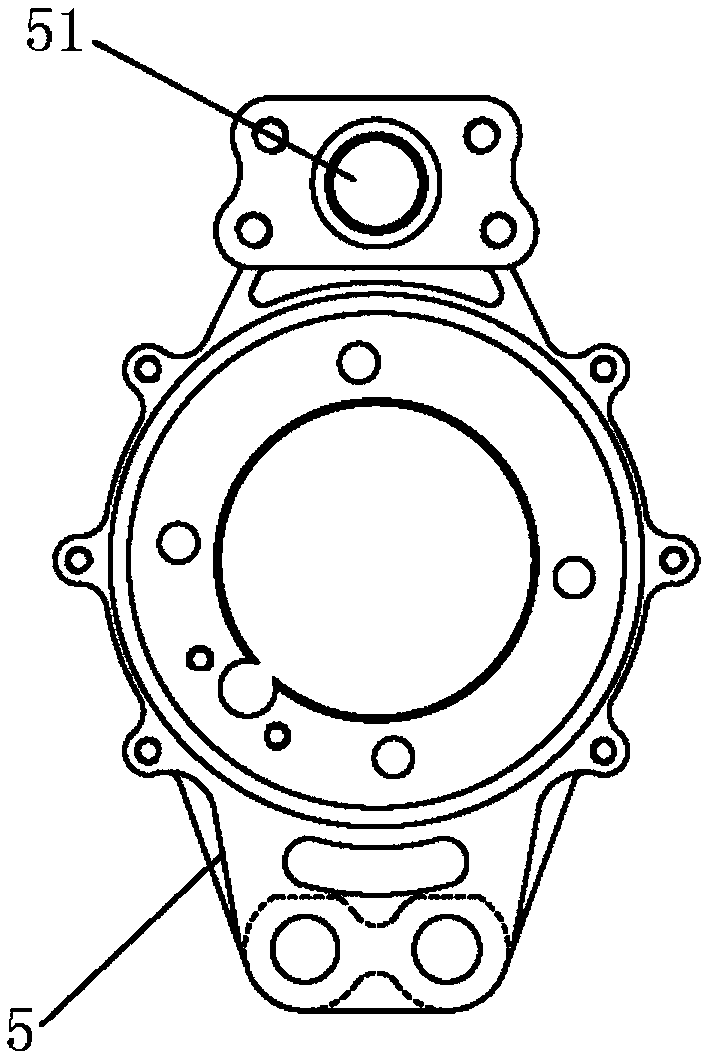
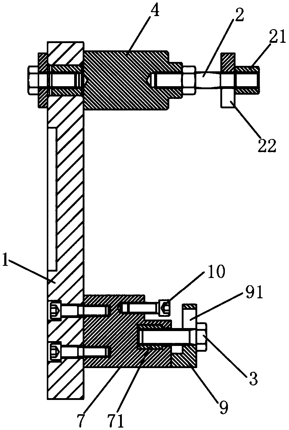
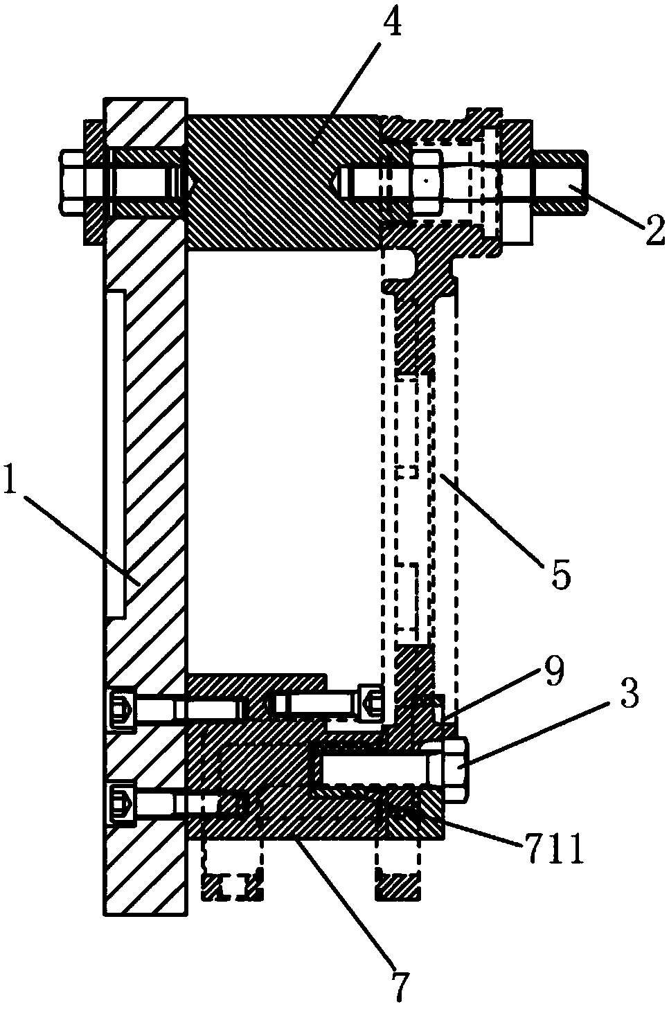
[0032] Such as Figure 1 to Figure 6 As shown, the turning fixture for the middle part of the brake base plate in this embodiment is a turning tool for the middle part of the brake base plate, which includes a base 1, a double-ended screw 2 and a bolt 3, and one end of the base 1 is provided with a fixed block 4, The double-ended screw 2 passes through the camshaft hole 51 of the brake base plate 5 to be processed and is fixedly connected with the fixed block 4, and the other end of the base 1 is provided with a mounting hole for laterally mounting the brake base plate 5. Positioned lateral positioning block 6 and two supporting blocks 7 for supporting the disc edge of the brake bottom plate 5, the lateral positioning block 6 is provided with a threaded hole...


PUM


Abstract

The invention relates to the technical field of tool clamps, in particular to a turning machining clamp for a middle disc surface of a brake bottom plate. The turning machining clamp comprises a base,a double-head screw and a bolt, wherein a fixing block is arranged at one end of the base, the double-head screw penetrates through a cam shaft hole of the brake bottom plate to be fixedly connectedwith the fixing block, the other end of the base is provided with a lateral positioning block and two supporting blocks, the side part of the supporting block is provided with an L-shaped pressing plate. The double-head screw and the fixing block are used for fixing one end of the brake bottom plate, the L-shaped pressing plate supporting block is used for fixing the other end of the brake bottomplate, then the center hole of the disc part of the brake bottom plate and the outer side face of the disc part are machined, then the inner side surface of the reverse hook cutter head part is utilized, machining of the two faces and the center hole adopts a positioning reference, the two surfaces of the annular disc surface of the braking bottom plate can be guaranteed to have relatively high parallelism, meanwhile, and the axis of the central hole and the annular disc surface can be ensured to have relatively high perpendicularity. According to the turning machining clamp for the middle disc surface of the brake bottom plate, the design is reasonable, the structure is simple, and the machining precision and quality of the brake bottom plate are improved.

Description

technical field [0001] The invention relates to the technical field of fixtures, in particular to a turning fixture for the disc surface of the middle part of a brake bottom plate. Background technique [0002] The automobile braking system is mainly composed of a brake drum, a brake base plate, a brake shoe, a brake transmission mechanism, etc. The brake base plate is the installation base of various parts in the automobile brake system. The braking principle of the automobile braking system is mainly to press the brake shoe on the inner side of the brake drum through the brake transmission mechanism, and the braking force generated by the friction of the shoe and the brake drum is transmitted to the brake bottom plate, and then Make the wheels slow down according to actual needs, or stop within the shortest distance to ensure driving safety. The brake base plate is the main force-bearing part in the automobile braking system and needs to bear a large load. Therefore, the ...

Claims


Application Information

Patent Timeline
Patent Type & Authority Applications(China)
IPC IPC(8): B23Q3/00
CPCB23Q3/00B23Q2703/10
Inventor 张奎陶德文张金刚邴浩孙阳徐华斌欧阳沐坤黄展
Owner HUBEI TRI RING AXLE
Learn More