
Casting piece grinding robot

A technology of robots and castings, which is applied in the direction of grinding machines, manufacturing tools, grinding workpiece supports, etc., can solve the problems of poor grinding effect and poor accuracy of arcs or depressions, so as to improve the quality of grinding and improve grinding Accuracy, the effect of improving the accuracy of grinding

Inactive Publication Date: 2019-04-09
ANHUI JISITE INTELLIGENT EQUIP CO LTD
View PDF7 Cites 2 Cited by
  • Summary
  • Abstract
  • Description
  • Claims
  • Application Information

AI Technical Summary

Problems solved by technology

[0003] However, in actual use, it still has some shortcomings, such as the existing equipment has a small range of grinding angles during grinding, and the grinding effect on arcs or depressions is not good, and the accuracy is not good.

Method used


Image

  • Casting piece grinding robot
  • Casting piece grinding robot
  • Casting piece grinding robot

Examples


Embodiment 1

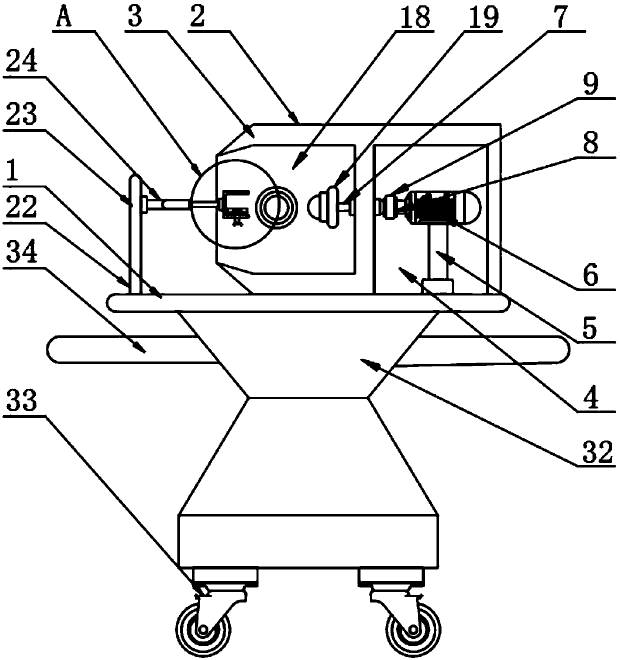
[0026] The present invention provides such Figure 1-5 The casting grinding robot shown includes a working platform 1, a grinding device 2 is provided on the top of the working platform 1, and the grinding device 2 includes a grinding box 3, and a first power chamber 4 is arranged inside the grinding box 3 , the inside of the first power chamber 4 is provided with a support rod 5, the support rod 5 is fixedly connected with the inner wall of the first power chamber 4, the top of the support rod 5 is provided with a servo motor 6, and one side of the servo motor 6 is provided There is a first rotating shaft 7, the output shaft of the servo motor 6 is fixedly connected with the first rotating shaft 7, a first gear 8 is provided on the outside of the first rotating shaft 7, and a tooth chain belt 9 is provided on the outside of the first gear 8, so The first gear 8 meshes with the toothed chain belt 9, the toothed chain belt 9 is provided with a second gear 10 inside, the second ...

Embodiment 2

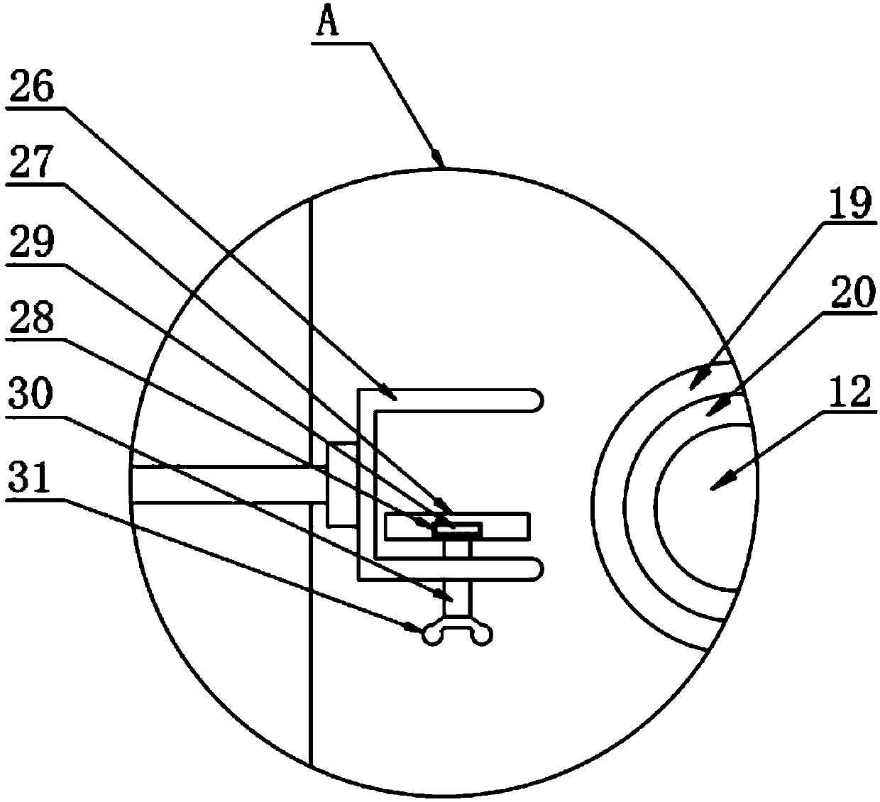
[0029] Further, in the above-mentioned embodiment 1, a fixing device 22 is provided on one side of the grinding box 3, and the fixing device 22 includes a side plate 23, and the side plate 23 is fixedly connected with the working platform 1;

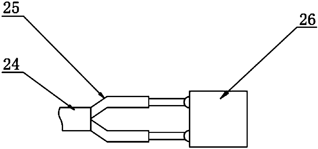
[0030] One side of the fixed plate 14 is provided with a connecting rod 24, and one side of the connecting rod 24 is provided with an electric telescopic rod 25;

[0031]One side of the electric telescopic rod 25 is provided with a fixed shell 26, and the output shaft of the electric telescopic rod 25 is hinged with the fixed shell 26. By setting the fixing device 22, the material is placed inside the fixed shell 26, and the button plate 31 is rotated. 31 Drive the rotary block 29 to rotate inside the limiting groove 28 through the screw rod 30, and then the brick pushes the pressing plate 27 to fix the material, and at the same time opens the electric telescopic rod 25, and the two electric telescopic rods 25 can push the fixed shell 26,...


PUM


Abstract

The invention discloses a casting piece grinding robot comprising a working platform. The top of the working platform is provided with a grinding device, the grinding device comprises a grinding box,the grinding box (3) is internally provided with a first power chamber, a support rod is arranged inside the first power chamber, the support rod is fixedly connected to the inner wall of the first power chamber, a servo motor is arranged on the top of the support rod, a first rotating shaft is arranged on one side of the servo motor, an output shaft of the servo motor is fixedly connected to thefirst rotating shaft, a first gear is arranged on the outer side of the first rotating shaft, a tooth chain belt is arranged on the outer side of the first gear, and the first gear is engaged with thetooth chain belt. The casting piece grinding robot is provided with the grinding device, a second grinding wheel can polish materials with deep sinking parts, a grinding ball can polish objects withlarge sinking ranges, the grinding areas of the materials are better improved, meanwhile, targeted grinding on the grinding radian can be carried out, the grinding precision is improved, and the grinding quality is improved.

Description

technical field [0001] The invention relates to the technical field of grinding, in particular to a casting grinding robot. Background technique [0002] The invention patent of patent application publication number CN107685268A discloses a casting grinding robot, including a base, a chute A and a cover on the base, a through hole on the cover, a rack in the through hole, and a chute on the rack B. There is a bump in the through hole, and the bump is in the chute B. There is motor A on the cover, gear A on motor A, motor B under the rack, gear B on motor B, and vertical gear under motor B. Rod A, there is a cross bar on the vertical rod A, there is a half gear on the cross bar, there are stoppers A and B on both sides of the half gear, there is a support rod under the half gear, there is a motor C under the support rod, and there is a grinding wheel on the motor C , there are sleeves, baffles and suction fans in the cover, vertical rod B in the sleeve, baffles on vertical r...

Claims


Application Information

Patent Timeline
Patent Type & Authority Applications(China)
IPC IPC(8): B24B19/00B24B27/00B24B47/12B24B41/06B24B47/22B24B41/04
CPCB24B19/00B24B27/0007B24B27/0076B24B41/04B24B41/06B24B47/12B24B47/22
Inventor 王兴松许飞云罗翔戴挺章功国
Owner ANHUI JISITE INTELLIGENT EQUIP CO LTD
Learn More