Vibration device for stirrer

A vibrating device, mixer technology, applied in the direction of cement mixing device, fluid using vibration, clay preparation device, etc.

Pending Publication Date: 2019-04-09
德通智能科技股份有限公司
View PDF11 Cites 2 Cited by
  • Summary
  • Abstract
  • Description
  • Claims
  • Application Information

AI Technical Summary

Problems solved by technology

[0004] The purpose of the present invention is to solve the common problems of structure, vibration effect and reliability of the vibration device of the existing vibration mixer that need to be further improved, and to provide a vibration device with simpler structure, better vibration effect and higher reliability. vibration device

Method used


Image

  • Vibration device for stirrer
  • Vibration device for stirrer
  • Vibration device for stirrer

Examples


Embodiment 1

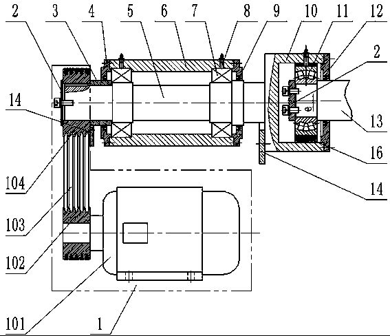
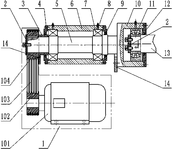
[0059] A vibration device for a mixer, comprising a vibration transmission device 1, a transmission shaft 5, a bearing I7, a bearing seat I6, a bearing II11, a bearing seat II10, and a stirring shaft 13. The transmission shaft 5 is a stepped shaft and is set through the bearing seat I6, and is supported and installed in the bearing seat I6 by two bearings I7. Bearing end covers 4 are respectively arranged at both ends of the bearing seat I6. On the bearing seat I6 Two lubricating oil passages 8 are provided, and the lubricating oil passages 8 respectively communicate with the oil passages of the outer ring of the bearing I7 for lubricating the bearing I7. The power source of the vibration transmission device 1 is a motor 101, a driving pulley 102 is installed on the output shaft of the motor 101, a driven pulley 104 is installed at one end of the transmission shaft 5, and a shaft end retaining ring is arranged at the end of the driven pulley 104 2. A positioning sleeve 3 is ar...

Embodiment 2

[0062] The difference from Example 1 is that an eccentric sleeve 16 is provided between the bearing seat II10 and the outer ring of the bearing II11, and the eccentric sleeve 16 can be a multi-shaft segment sleeve part, and the preferred single-shaft segment eccentric sleeve 16 is used for installation The centerline of the inner hole of the bearing II11 is eccentrically set relative to the centerline of rotation of the transmission shaft 5 , so that the centerline of rotation of the transmission shaft 5 is offset from the axis of the outer raceway of the bearing II11 .

Embodiment 3

[0064]The difference from Example 1 is that the bearing II11 is an eccentric bearing of the outer ring, and the eccentric bearing of the outer ring refers to a bearing in which the center line of the outer circle of the outer ring is eccentric to the axis of the outer raceway, and the axis of the outer raceway It refers to the centerline of the outer raceway along the axial direction of the transmission shaft 5, so that the rotation centerline of the transmission shaft 5 is offset from the axis of the outer raceway of the bearing II11.


PUM


Abstract

The invention relates to the technical field of stirring machines, in particular to a vibration device for a stirrer. The vibration device comprises a vibration transmission device, a transmission shaft, bearings I, a bearing block I, a bearing II, a bearing block II and a stirring shaft, the transmission shaft penetrates through the bearing block I and is supported in the bearing block I throughat least two bearings I, one end of the transmission shaft is connected with the vibration transmission device, the other end of the transmission shaft is fixedly connected with the bearing block II,the bearing block II is connected with a shaft head at one end of the stirring shaft through the bearing II, and the rotation center line of the transmission shaft is offset from the axis of the outerroller way of the bearing II. The vibration device for the stirrer has the advantages of being simple in structure, good in vibration effect and high in reliability.

Description

technical field [0001] The invention belongs to the technical field of mixers, in particular to a vibrating device for mixers. Background technique [0002] A mixer is a machine that can mix a variety of raw materials into a specific mixture. According to the mixing method, it can be divided into two categories: forced mixer and self-falling mixer. Among them, the forced mixer is favored by customers because of its good mixing quality and high mixing efficiency. It is currently the mainstream mixing equipment at home and abroad. With the continuous improvement of users' requirements for mixing quality and the emergence of new materials, especially materials that are more difficult to mix, higher requirements are put forward for the technical performance and reliability of traditional mixing equipment. Take the cement concrete mixer as an example: the traditional forced mixer belongs to "static mixing", and there are common problems such as high energy and raw material consu...

Claims


Application Information

Patent Timeline
Patent Type & Authority Applications(China)
IPC IPC(8): B28C5/48
CPCB28C5/48B06B1/16B28C5/14
Inventor 张良奇李冠峰孔鲜宁
Owner 德通智能科技股份有限公司
Why Eureka
Try Eureka