Optical mechanism

An optical mechanism and optical lens technology, applied in the field of photocuring, can solve the problems of low UV energy and optical power density, and achieve the effect of improving photocuring effect and production efficiency, UV energy and optical power density

Pending Publication Date: 2019-04-09
深圳市瑞丰光电紫光技术有限公司
View PDF0 Cites 1 Cited by
  • Summary
  • Abstract
  • Description
  • Claims
  • Application Information

AI Technical Summary

Problems solved by technology

[0003] In order to overcome the deficiencies of the prior art, the present invention provides an optical mechanism for solving the problem of UV energy and light existing in the prior art by pasting lamp beads on the circuit board to form a module and then adding a glass lens above the light source. The problem of low power density

Method used


Image

  • Optical mechanism
  • Optical mechanism
  • Optical mechanism

Examples


Embodiment Construction

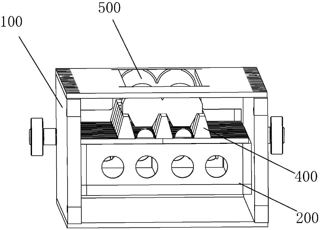
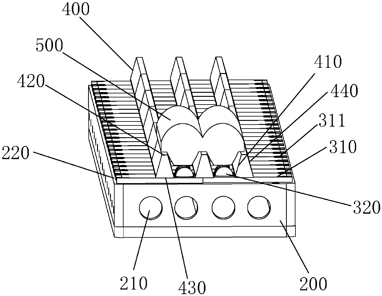
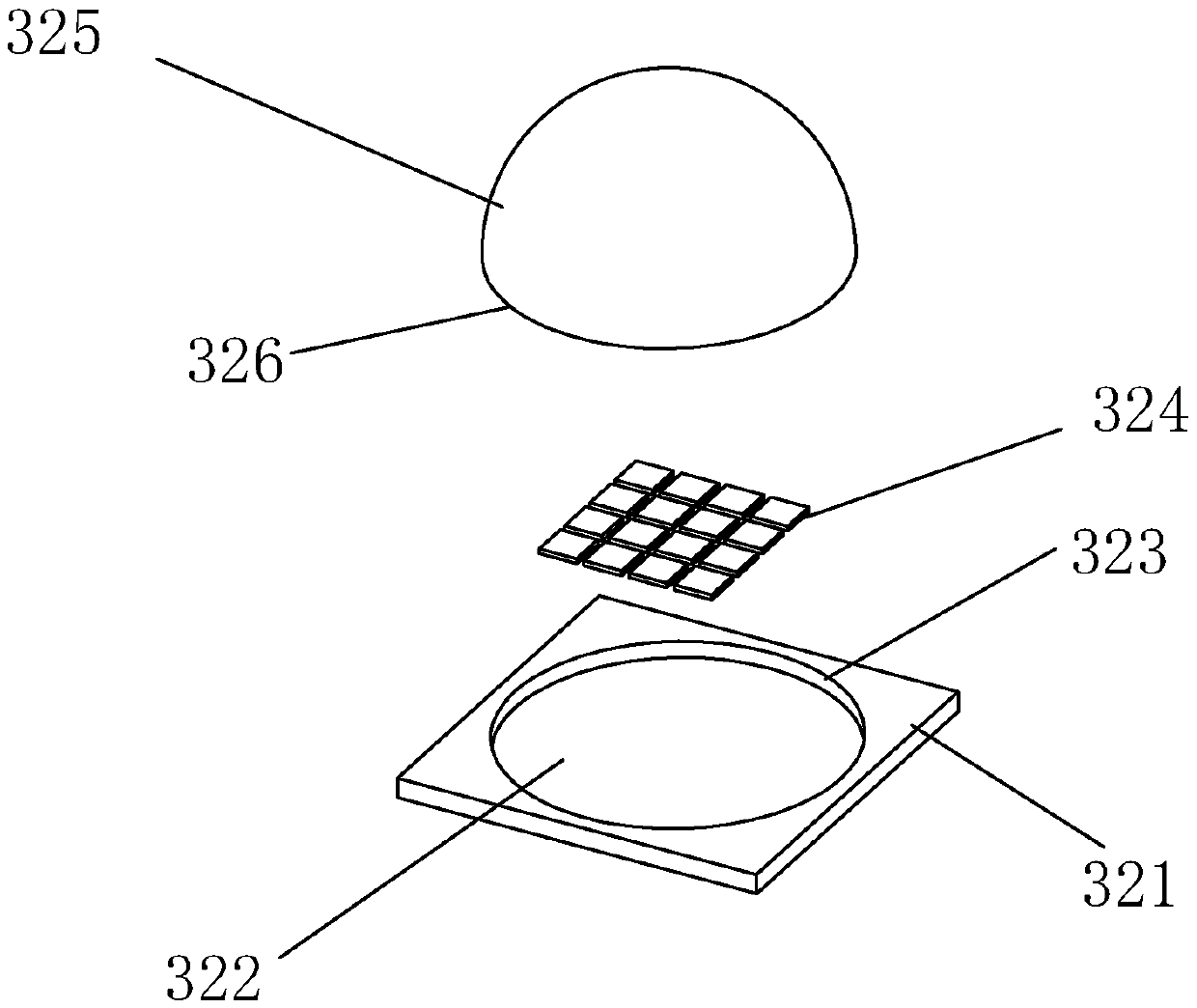
[0023] In the following, the conception, specific structure and technical effects of the present invention will be clearly and completely described in conjunction with the embodiments and drawings, so as to fully understand the purpose, scheme and effect of the present invention. It should be noted that, in the case of no conflict, the embodiments in the present application and the features in the embodiments can be combined with each other.

[0024] It should be noted that, unless otherwise specified, when a feature is called "fixed" or "connected" to another feature, it can be directly fixed and connected to another feature, or indirectly fixed and connected to another feature. on a feature. In addition, descriptions such as up, down, left, right, front, and back used in the present invention are only relative to the mutual positional relationship of the components of the present invention in the drawings.

[0025] Also, unless defined otherwise, all technical and scientifi...


PUM


Abstract

The invention relates to the technical field of photo-curing, in particular to an optical mechanism for offset printing light curing. The optical mechanism comprises a shell, a heat dissipation device, a light source assembly and a first optical lens, wherein the heat dissipation device is arranged in the shell, the light source assembly comprises LED lamp beads and a first substrate for bearing the LED lamp beads, the first optical lens is arranged right front of the LED lamp bead, so that light rays emitted by the LED lamp beads are converged; the heat dissipation device is propped against the substrate, and the LED lamp beads comprise a plurality of chips. A quartz glass sheet or a cylindrical quartz glass rod of a flat plate adopted by a traditional UV-LED light source is changed intoa special-shaped quartz glass, the LED lamp beads packaged in the 16 PCS purple light chips are combined and closely arranged, so that the light source UV energy and the optical power density are greatly improved, the light curing effect and the production efficiency are improved.

Description

technical field [0001] The invention relates to the field of light curing technology, in particular to an optical mechanism for offset printing light curing. Background technique [0002] UV-LED light source has the characteristics of long service life, high reliability, high luminous efficiency, low power consumption, no heat radiation, and environmental protection. In recent years, it has been more and more widely used in UV curing and printing, especially In the fields of high-power offset printing and varnish machines, high-power-density UV-LED light source modules have been adopted by most equipment factories. At present, most of the light source heads of equipment in the industry are composed of lamp beads pasted on circuit boards such as copper substrates. The UV-LED module is realized by adding light-emitting sheets and glass lenses. This method is composed of a single lamp bead. Since a lot of lamp beads need to be pasted on the light source head, the production eff...

Claims


Application Information

Patent Timeline
Patent Type & Authority Applications(China)
IPC IPC(8): B41F23/04
CPCB41F23/04
Inventor 吴慧文王姣
Owner 深圳市瑞丰光电紫光技术有限公司
Why Eureka
Try Eureka