Vehicle front pillar assembly and automobile

A vehicle front pillar and assembly technology, applied in the field of vehicle parts, can solve the problems of hidden safety hazards for passengers and drivers, low strength of the main structure of the front pillar, unfavorable force transmission, etc., to ensure driving safety and structural strength , Improving vehicle collision safety and improving market competitiveness

Active Publication Date: 2020-08-14
WM MOTOR TECH GRP CO LTD
View PDF6 Cites 0 Cited by
  • Summary
  • Abstract
  • Description
  • Claims
  • Application Information

AI Technical Summary

Problems solved by technology

The inventor found in the process of realizing the invention that the top and bottom of the above-mentioned facade structure 1' have the following deficiencies in the connection: first, the outer reinforcement plate 2' of the vehicle body is arranged obliquely, and the connection reinforcement plate at the top of the facade structure 1' It is bent and connected with the outer reinforcement plate 2' of the vehicle body, and the connection reinforcement plate at the bottom of the facade structure 1' is set nearly vertically with the threshold 3', and the connection reinforcement plate at the bottom of the facade structure 1' is also connected with the threshold 3' by bending; In the case of a frontal high-speed collision, the above two turning joints cannot effectively transmit the force to the rear of the vehicle, and the two turning places are prone to twisting and bending, which is not conducive to the dispersion of force transmission; second, the main structure of the front pillar is low in strength and Poor stability, prone to improper support and protection in frontal collision or offset collision, resulting in serious impact deformation of the passenger compartment, and serious safety hazards to the driving safety of passengers and drivers

Method used


Image

  • Vehicle front pillar assembly and automobile
  • Vehicle front pillar assembly and automobile
  • Vehicle front pillar assembly and automobile

Examples


Embodiment Construction

[0021] The directional terms such as up, down, left, right, front, back, front, back, top, and bottom that are mentioned or may be mentioned in this specification are defined relative to the structures shown in the drawings. The words " "Inside" and "outside" respectively refer to the direction toward or away from the geometric center of a specific component. They are relative concepts, so they may change accordingly according to their different positions and different usage states. Accordingly, these or other directional terms should not be construed as limiting terms.

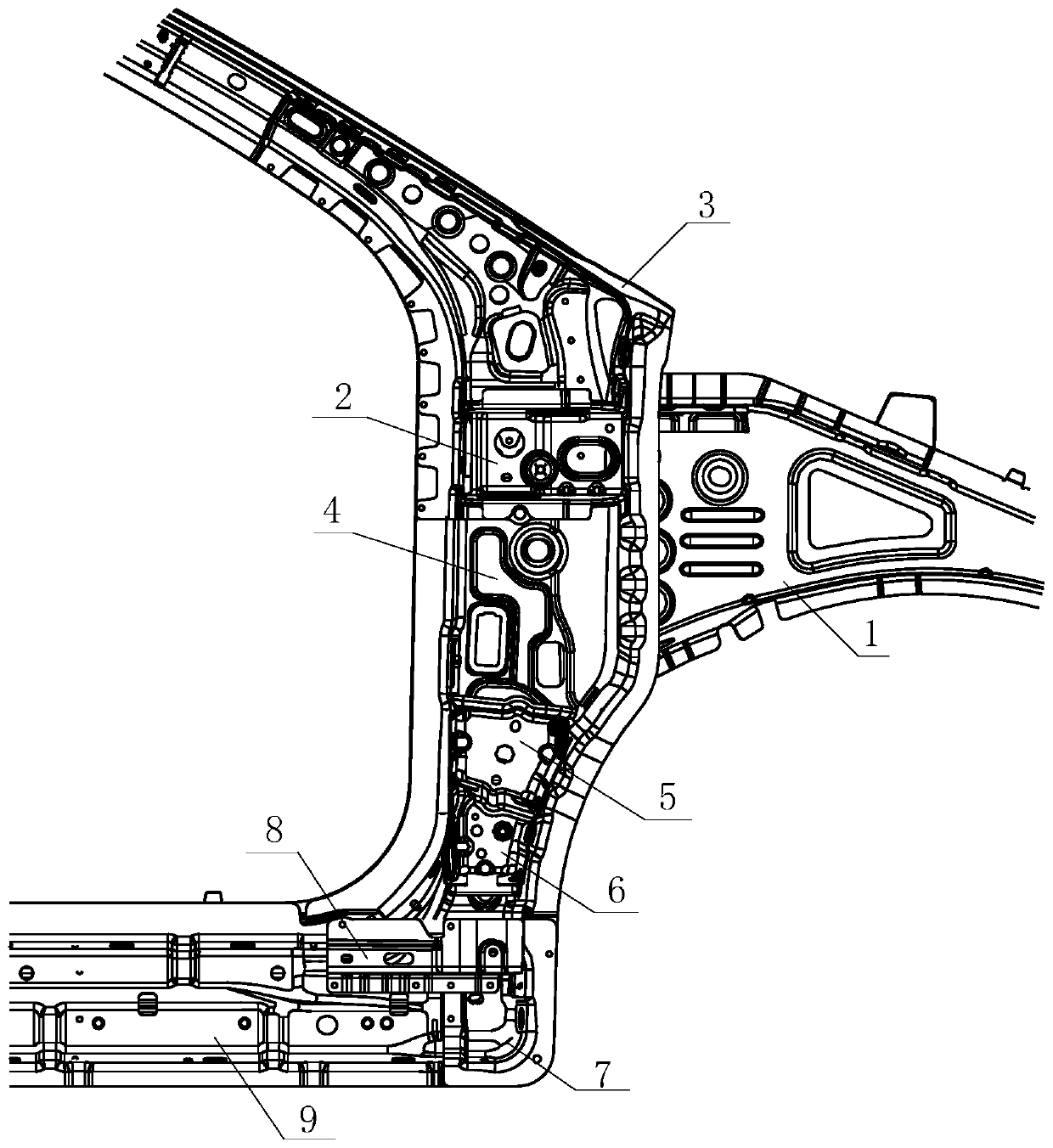
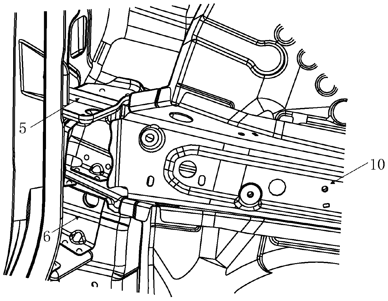
[0022] figure 2 A schematic structural view of the front pillar provided for an optional embodiment of the present invention, image 3 A schematic diagram of the structure of the front wall support plate installed on the lower hinge plate provided by the optional embodiment of the present invention. Such as Figure 2 to Figure 3 As shown, an optional embodiment of the present invention provides a vehicle ...


PUM


Abstract

The invention discloses a vehicle front column assembly and an automobile. The vehicle front column assembly comprises an upper reinforcing plate, a lower reinforcing plate, an upper hinge plate, a front column supporting plate, a lower hinge plate and a front wall supporting plate, wherein the upper reinforcing plate and the lower reinforcing plate are independently molded and connected with eachother; the upper hinge plate is arranged on the upper reinforcing plate; the front column supporting plate and the lower hinge plate are independently molded and connected with each other; the frontcolumn supporting plate is connected to one side, facing away from the upper reinforcing plate, of the lower reinforcing plate; the lower hinge plate faces away from the lower reinforcing plate; and the front wall supporting plate is connected to the connecting part of the lower hinge plate and the front column supporting plate. The automobile comprises a front wheel cover side sill outer panel and the vehicle front column assembly; and the upper reinforcing plate and the lower reinforcing plate are both connected with the front wheel cover side sill outer panel in a laminated manner. According to the vehicle front column assembly and the automobile, the anti-bending capacity of a front column during high speed frontal collision or biasing collision is improved, the stress is effectively dispersed, the deformation of the front column during high speed frontal collision or biasing collision is reduced, the stability of the front column is kept, and the safety of the whole automobile isenhanced.

Description

technical field [0001] The invention relates to the technical field of vehicle parts, in particular to a vehicle front pillar assembly and an automobile. Background technique [0002] The front pillars are located on both sides of the vehicle, and are connecting pillars that connect the roof and the front cabin, while being inclined at a predetermined angle to support the front doors. [0003] figure 1 It is a structural schematic diagram of the front pillar in the prior art. Such as figure 1 As shown, in the prior art, the front pillar includes a facade structure 1' inside the vehicle body and an external reinforcement plate 2' of the vehicle body, and the top and bottom of the facade structure 1' are provided with connecting reinforcement plates, which are located in the facade structure 1' The connection reinforcement plate at the top is connected with the outer reinforcement plate 2' of the vehicle body; the connection reinforcement plate at the bottom of the facade s...

Claims


Application Information

Patent Timeline
Patent Type & Authority Patents(China)
IPC IPC(8): B62D25/04B62D27/02
CPCB62D25/04B62D27/02
Inventor 冉崇琪唐东升
Owner WM MOTOR TECH GRP CO LTD
Why Eureka
Try Eureka