
Adjustable pull rod assembly

An adjustable, pull-rod technology, applied in aircraft parts, transportation and packaging, can solve problems such as fairing tearing, and achieve the effect of avoiding forced assembly, excellent stability, and reduced quantity

Inactive Publication Date: 2019-04-09
XIAN AIRCRAFT DESIGN INST OF AVIATION IND OF CHINA
View PDF0 Cites 5 Cited by
  • Summary
  • Abstract
  • Description
  • Claims
  • Application Information

AI Technical Summary

Problems solved by technology

[0002] The main fairing of the aircraft is used as a secondary load-bearing structure. Its design needs to meet the requirements of function, strength, and stiffness, and the weight should be as light as possible. It should not participate in the overall force of the fuselage. Try not to use a completely riveted form, so that the inconsistency of the rigidity deformation of the fuselage and the main fairing during flight may lead to the tearing of the fairing
Therefore, the connection between the main fairing and the fuselage needs to be designed in a form that has a large amount of compensation and is easy to assemble and adjust, which cannot be satisfied by existing devices.

Method used


Image

  • Adjustable pull rod assembly
  • Adjustable pull rod assembly
  • Adjustable pull rod assembly

Examples


Embodiment Construction

[0020] In order to make the objectives, technical solutions and advantages of the present invention clearer, the technical solutions in the embodiments of the present invention will be described in more detail below in conjunction with the drawings in the embodiments of the present invention. In the drawings, the same or similar reference numerals denote the same or similar elements or elements having the same or similar functions throughout. The described embodiments are some, but not all, embodiments of the invention. The embodiments described below by referring to the figures are exemplary and are intended to explain the present invention and should not be construed as limiting the present invention. Based on the embodiments of the present invention, all other embodiments obtained by persons of ordinary skill in the art without creative efforts fall within the protection scope of the present invention.

[0021] The adjustable pull rod assembly of the present invention will...


PUM


Abstract

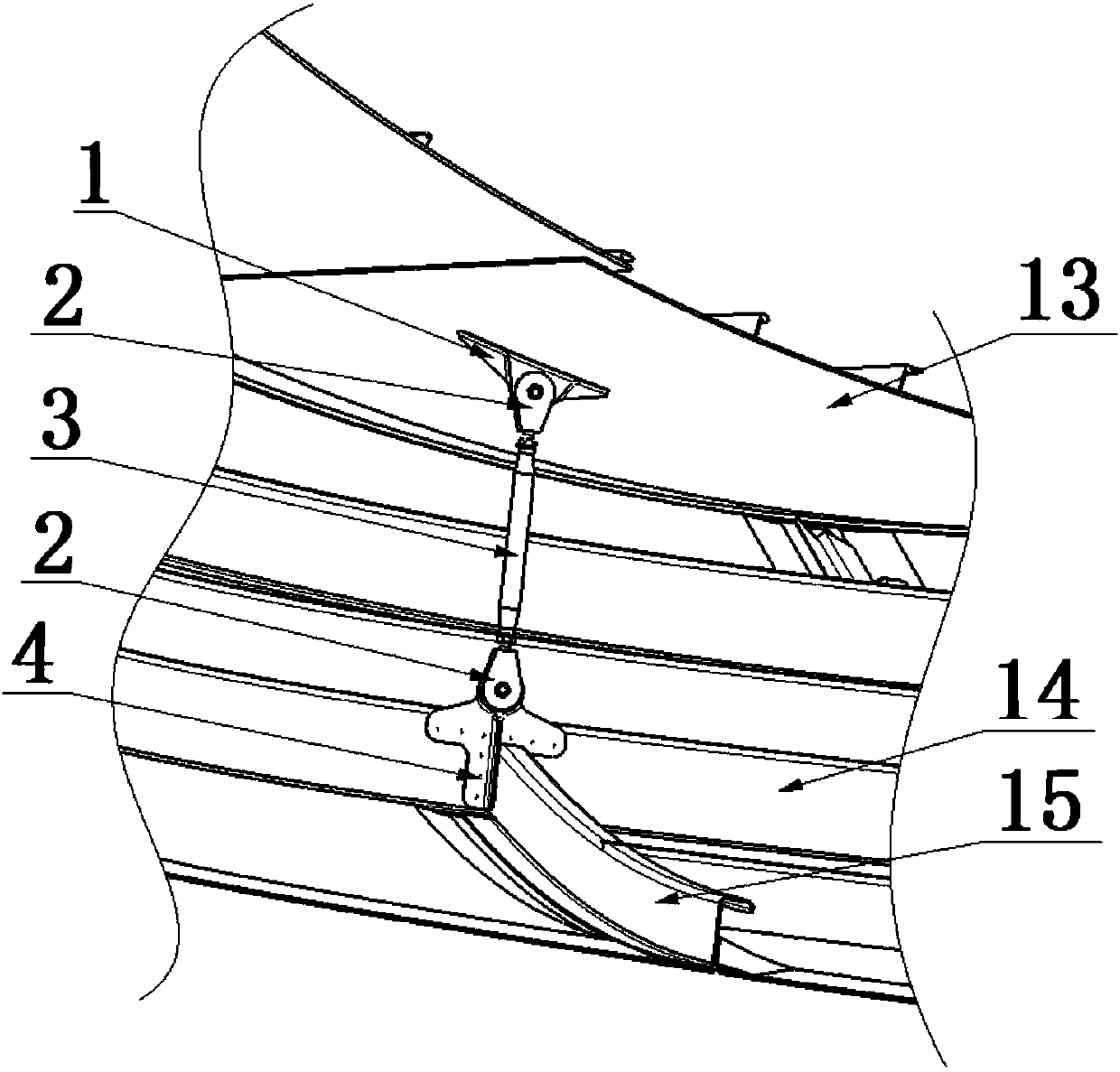
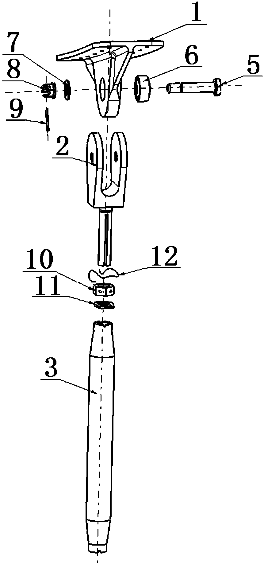
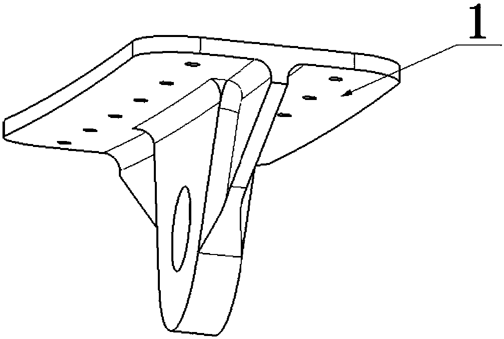
The invention provides an adjustable pull rod assembly which comprises an upper support (1), a fork lug connector (2), a lower support (4) and a closing pull rod (3); the upper support (1) is composedof a base and a single lug piece perpendicularly connected with the base, and the base is installed on a machine body wall plate (13); the fork lug connector (2) is composed of a U-shaped double-lug-piece component and a rod-shaped piece connected with the U-shaped double-lug-piece component. The lower support (4) comprises an annular component and a T-shaped flat plate component connected with the outer diameter of the annular component; one side of the T-shaped flat plate component is used for being connected with a main fairing frame (14), and the other side of the T-shaped flat plate component is connected with a main fairing longitudinal beam (15) through a vertical rib vertically arranged on the T-shaped flat plate component; and the closing pull rod (3) is a tubular component, androd-shaped pieces of the fork lug connector (2) are inserted into the two ends of the closing pull rod (3) so that the closing pull rod is fitted with the single lug piece in the upper support (1) andthe annular component in the lower support (4) for installation. The adjustable pull rod assembly reduces the number of parts, and the parts are easy to manufacture, simple and convenient to assembleand convenient to adjust.

Description

technical field [0001] The invention belongs to the field of aircraft structure design, and in particular relates to an adjustable tie rod assembly. Background technique [0002] The main fairing of the aircraft is used as a secondary load-bearing structure. Its design needs to meet the requirements of function, strength, and stiffness, and the weight should be as light as possible. It should not participate in the overall force of the fuselage. Try not to use a completely riveted form, which may cause the fairing to tear due to inconsistent rigidity deformation between the fuselage and the main fairing during flight. Therefore, the connection between the main fairing and the fuselage needs to be designed in a form that has a large amount of compensation and is easy to assemble and adjust, which cannot be satisfied by existing devices. Contents of the invention [0003] It is an object of the present invention to provide an adjustable tie rod assembly that overcomes or al...

Claims


Application Information

Patent Timeline
Patent Type & Authority Applications(China)
IPC IPC(8): B64C7/00
CPCB64C7/00
Inventor 刘叶彭嫪丁燕刘蓬
Owner XIAN AIRCRAFT DESIGN INST OF AVIATION IND OF CHINA
Learn More