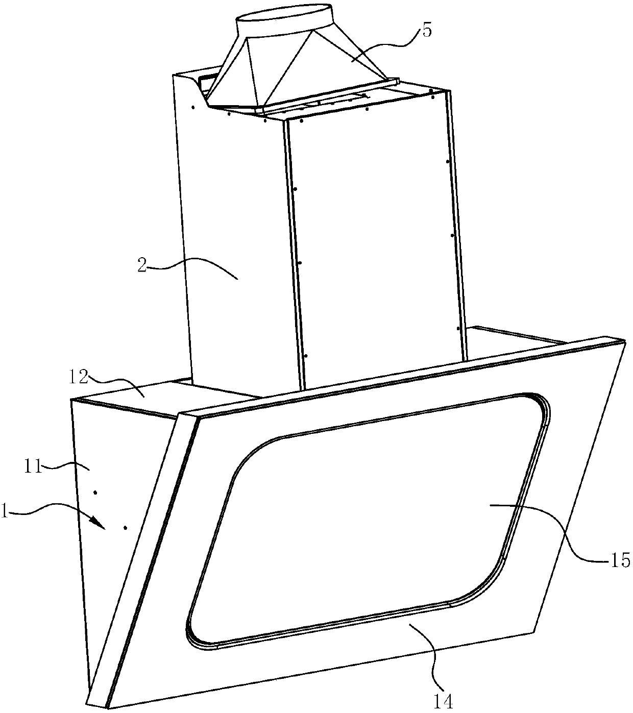
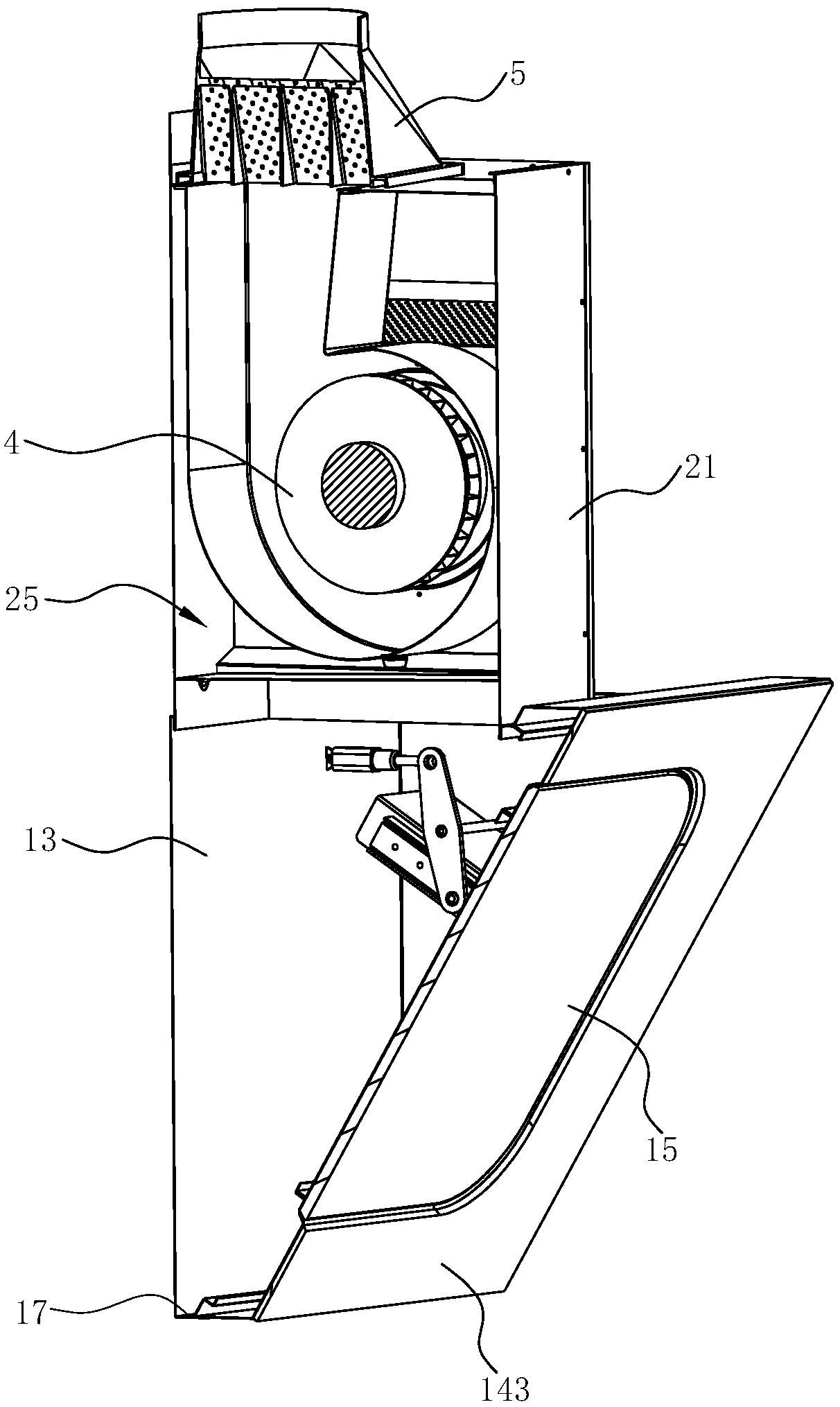
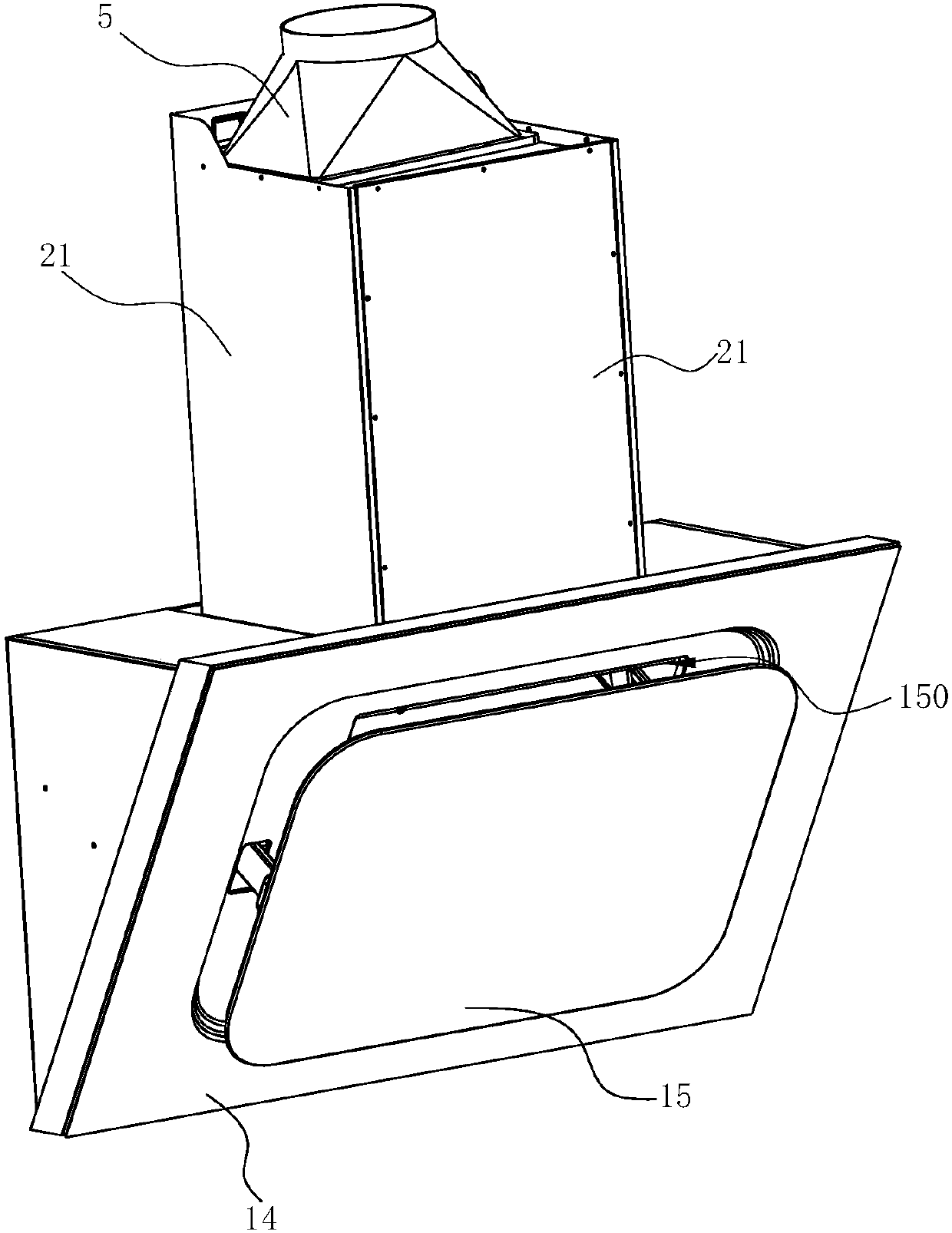
Near-suction type range hood

A range hood and near-suction technology, which is applied in the field of kitchen appliances, can solve problems such as the inability to effectively block the smell of oil fume, difficulty in overcoming pipeline resistance, and unfavorable impeller work ability, so as to improve the smoke exhaust effect, increase the efficiency of range hood, The effect of a large negative pressure gradient

Inactive Publication Date: 2019-04-09
NINGBO FOTILE KITCHEN WARE CO LTD
View PDF3 Cites 3 Cited by
  • Summary
  • Abstract
  • Description
  • Claims
  • Application Information

AI Technical Summary

Problems solved by technology

[0004] In the prior art solution as mentioned above, the middle panel is fixed, and there is a gap between the middle panel and the outer panel for smoke inhalation. The gap has been determined during the original design and manufacture, so the gap is permanently open. , so that the smoke collection hood and the flue are straight through, the smoke baffle cannot effectively block the odor of other users in the flue of the whole building, which will bring great inconvenience to users and environmental pollution; the fan system usually adopts multi-blade centrifugal fan, and the multi-blade centrifugal fan is placed in the lower triangle. In order to ensure a high air intake efficiency, the fan system is relatively large
Moreover, this arrangement of the fan, because the impeller has a pre-rotation effect on the gas and the direction of the gas will gradually change during the 90° turning process of the gas flowing into the impeller, the purely consistent inlet and outlet angles are not good for the actual working ability of the impeller. ;In addition, the fan is far away from the air outlet pipe, it is difficult to overcome the resistance of the pipe, the fan faces the user directly, lacks noise reduction measures, and the noise is high

Method used


Image

  • Near-suction type range hood
  • Near-suction type range hood
  • Near-suction type range hood

Examples


Embodiment 2

[0050] see Figure 10 and Figure 11 , in this embodiment, the difference from the first embodiment above is that the first ternary fan system 41 and the second ternary fan system 42 share the same volute 44, that is, the first ternary fan system 41 of the first ternary fan system 41 The first three-way impeller 412 and the second three-way impeller 422 of the second three-way blower system 42 are both arranged in the same volute 44 .

[0051] A mounting plate 45 is arranged between the two ternary impellers, thereby separating the two ternary impellers on both sides of the mounting plate 45, and the mounting plate 45 extends to the top of the volute 44, thereby dividing the volute 44 into two The first oil fume passage 441 and the second oil fume passage 442 are independent. The driving motor 43 passes through the mounting plate 45 and is connected and fixed with the mounting plate 45 .

[0052] In this embodiment, the air outlet cover 5 only includes a cover body 51 and a...


PUM


Abstract

The invention discloses a near-suction type range hood. The near-suction type range hood comprises a shell and a fan system, wherein the shell comprises a panel which is located at the front end and is inclined relative to the horizontal direction, an opening is formed in the panel to form an air inlet of the range hood, the near-suction type range hood is characterized in that the fan system comprises a first three-dimensional fan and a second three-dimensional fan which are arranged in parallel, the fan system is arranged in a machine box, a smoke guide plate is arranged on the front side ofthe panel, a gap between the smoke guide plate and the panel forms an air inlet channel, and the air inlet channel communicates with the shell through the opening. When the range hood does not work,by closing the smoke guide plate, a relatively smeary filter screen and the fan system can be hidden, so that the range hood is kept clean and tidy; and when the range hood works, by opening the smokeguide plate, air at the periphery of the shell can be guided, airflow passing through an outer flow adjusting layer can be effectively segmented, adjusted and guided, then turbulent flow and disorderly flow in the airflow are reduced, the smooth airflow is formed, namely, the smoke collecting area of the shell is increased equivalently, and the smoke exhausting effect of the range hood can be well improved.

Description

technical field [0001] The invention relates to kitchen appliances, in particular to a near-suction range hood. Background technique [0002] Range hoods have become one of the indispensable kitchen appliances in modern families. Generally, range hoods include top-suction and near-suction range hoods. Near-suction range hoods use vortex wind pressure to move away, and absorb most of the fumes that are close to the stove in an arc, which can reduce adverse effects on human health. Influence, and the power source is closer to the stove, basically it will not reduce the suction effect of the power source. [0003] For example, a side suction range hood disclosed in Chinese Patent Application No. 201110338726.2 includes: an outer panel with a first middle opening; a middle panel arranged at the first middle opening of the outer panel, and the gap between the outer panel A smoke inlet is formed; the smoke collection chamber is located on the inner side of the outer panel and co...

Claims


Application Information

Patent Timeline
Patent Type & Authority Applications(China)
IPC IPC(8): F24C15/20
CPCF24C15/20
Inventor 周佳杰梁雪斐王艳辉董一龙茅忠群诸永定刘戈
Owner NINGBO FOTILE KITCHEN WARE CO LTD
Why Eureka
Try Eureka