
Welding plate heat exchanger

A technology for heat exchangers and welded plates, which is applied in the direction of indirect heat exchangers, heat exchanger types, heat exchanger fixation, etc., which can solve the problems of easy aging of rubber gaskets, affecting equipment operation, and poor heat exchange effect of plate heat exchangers. advanced questions

Pending Publication Date: 2019-04-09
浙江干氏制冷设备有限公司
View PDF0 Cites 2 Cited by
  • Summary
  • Abstract
  • Description
  • Claims
  • Application Information

AI Technical Summary

Problems solved by technology

The structure is relatively complicated and because the rubber gasket is easy to age at high temperature and loses its sealing effect, resulting in a large amount of fluid leakage, which endangers the safety of the equipment; in addition, the rubber gasket also has compatibility problems with the fluid. It cannot be used in corrosive fluids, which limits the range of use of the plate heat exchanger; in addition, due to the high degree of turbulence in some areas of the plate heat exchanger, when the fluid flows, the exchange The hot plate produces a large stamping force, which deforms the heat exchange plate under the action of the stamping force, which may cause fluid leakage in severe cases; in addition, the heat exchange effect of the current plate heat exchanger is not high, and the plate heat exchange There is a stagnant area of ​​fluid at the inlet and outlet of the fluid, and the fluid flow rate is low, resulting in continuous deposition and formation of dirt, which will eventually block the flow channel and affect the operation of the equipment

Method used


Image

  • Welding plate heat exchanger
  • Welding plate heat exchanger
  • Welding plate heat exchanger

Examples


Embodiment Construction

[0015] In order to enable those skilled in the art to better understand the solutions of the present invention, the technical solutions in the embodiments of the present invention will be clearly and completely described below in conjunction with the drawings in the embodiments.

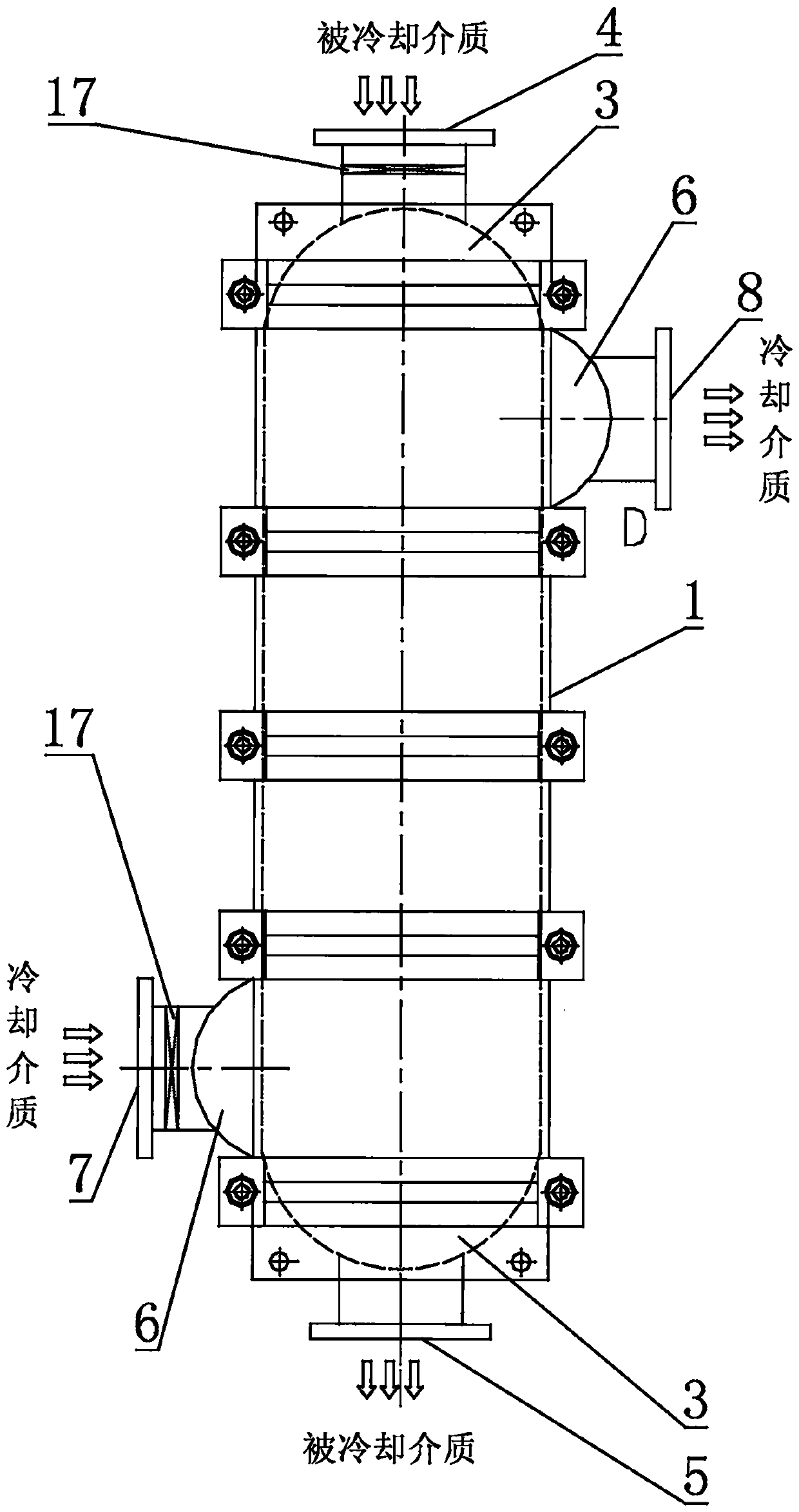
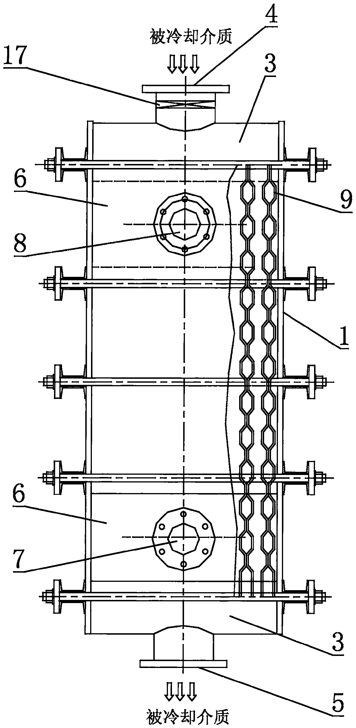
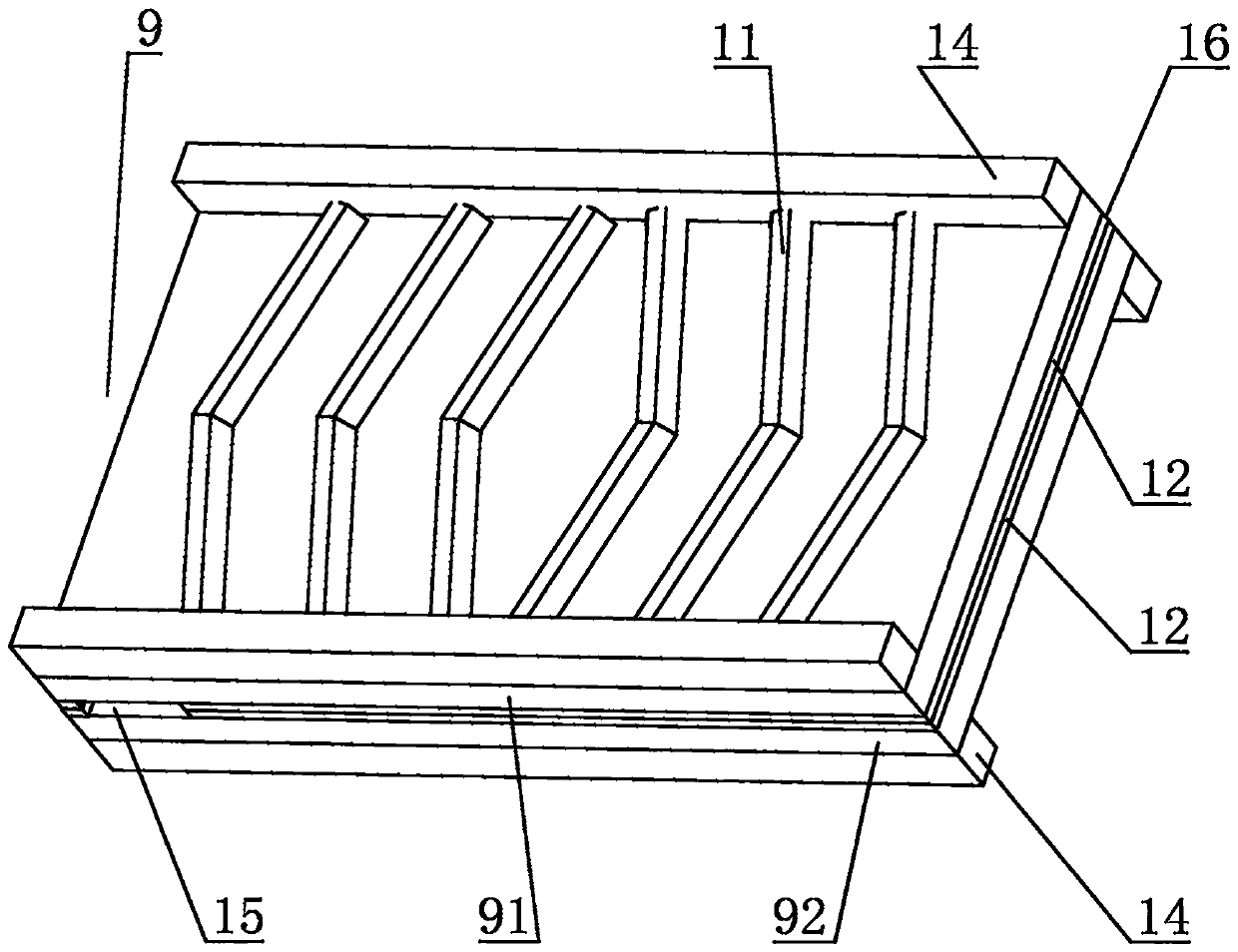
[0016] Such as figure 1 , figure 2 , image 3 , Figure 4 , Figure 5 , Image 6 , Figure 7 As shown, the present invention discloses a welded plate heat exchanger, comprising a shell 1 and a heat exchange plate group 2 arranged inside the shell 1, the shell 1 is rectangular and arranged horizontally, the Both ends of the housing 1 are provided with large semi-circular tube boxes 3, one of which is provided with a cooling medium inlet 4 on the top of the semi-circular tube box 3, and a cooling medium inlet 4 is provided on the top of the other large semi-circular tube box 3. Outlet 5, a small semi-circular tube box 6 is provided on the upper shell wall of the housing 1 close to the inlet 4 of...


PUM


Abstract

The invention discloses a welding plate heat exchanger. The welding plate heat exchanger comprises a shell and a heat exchange plate set inside the shell; the shell is rectangular and horizontally arranged; large half round channels are arranged at the two ends of the shell; the top of one of the large half round channels is provided with a cooled medium inlet; the top of the other large half round channel is provided with a cooled medium outlet; a small half round channel is arranged on the shell wall of the upper side, close to the cooled medium inlet, of the shell; the top of the small halfround channel is provided with a cooling medium outlet; a small half round channel is arranged on the shell wall of the lower side, close to the cooled medium outlet, of the shell; the top of the small half round channel is provided with a cooling medium inlet; the heat exchange plate set is formed by overlapping a plurality of heat exchange plate pair layer by layer; and each heat exchange platepair comprises an upper heat exchange plate and a lower heat exchange plate which are opposite. The effects that the welding plate heat exchanger can bear high temperature, is resistant to corrosion,high in intensity, not prone to deforming, not prone to being blocked and high in heat exchange efficiency can be achieved.

Description

technical field [0001] The invention relates to a plate heat exchanger, in particular to a welded plate heat exchanger. Background technique [0002] Heat exchangers (also known as heat exchangers or heat exchange equipment) are used to transfer heat from hot fluid to cold fluid, and can be divided into coil-plate heat exchangers, plate heat exchangers, and shell-and-tube heat exchangers according to their structure . The traditional plate heat exchanger is composed of a group of rectangular thin metals arranged in parallel and tightly assembled on the bracket. The edges of the adjacent plates are provided with rubber gaskets, and a sealed fluid channel is formed between the plates after compression, and the size of the channels can be adjusted by the thickness of the rubber gaskets. On the four corners of each plate, a circular hole is opened, and a pair of circular holes communicate with the flow channels between a group of plates, and the other pair of circular holes pr...

Claims


Application Information

Patent Timeline
IPC IPC(8): F28D9/00F28F3/04F28F3/08F28F19/01
CPCF28D9/0043F28F3/044F28F3/08F28F19/01F28F2275/06
Inventor 赵强彪干苗根张雁雷张春明丁秋华金志刚周建成
Owner 浙江干氏制冷设备有限公司
Learn More