Novel 900-t/d high-heat-value domestic garbage incinerator

A domestic waste incineration and high calorific value technology, applied in the direction of incinerators, combustion methods, combustion types, etc., can solve problems such as uneven temperature distribution on both sides of the flue, affecting the service life of the furnace wall, and overheating of the front arch wall. It is beneficial to the secondary combustion, improves the comprehensive heat utilization rate, and has the effect of low failure rate

Pending Publication Date: 2019-11-08
GUANGZHOU HUANTOU DESIGN & RES INST CO LTD
View PDF0 Cites 1 Cited by
  • Summary
  • Abstract
  • Description
  • Claims
  • Application Information

AI Technical Summary

Problems solved by technology

[0007] 2. The upper part of the waste burning area is the front arch furnace wall of the furnace. The flue gas generated by the combustion often enters the flue against the front arch. Due to the high temperature of the flue gas and the high concentration of acid gas and fly ash particles in the flue gas, It is easy to cause overheating, corrosion, wear and coking on the front arch wall surface, which will affect the service life of the furnace wall
The flue gas enters the flue along the front arch, resulting in high flue gas temperature near the front wall of the flue, and uneven temperature distribution on both sides of the flue, which is not conducive to the SNCR reaction

Method used


Image

  • Novel 900-t/d high-heat-value domestic garbage incinerator
  • Novel 900-t/d high-heat-value domestic garbage incinerator
  • Novel 900-t/d high-heat-value domestic garbage incinerator

Examples


Embodiment 1

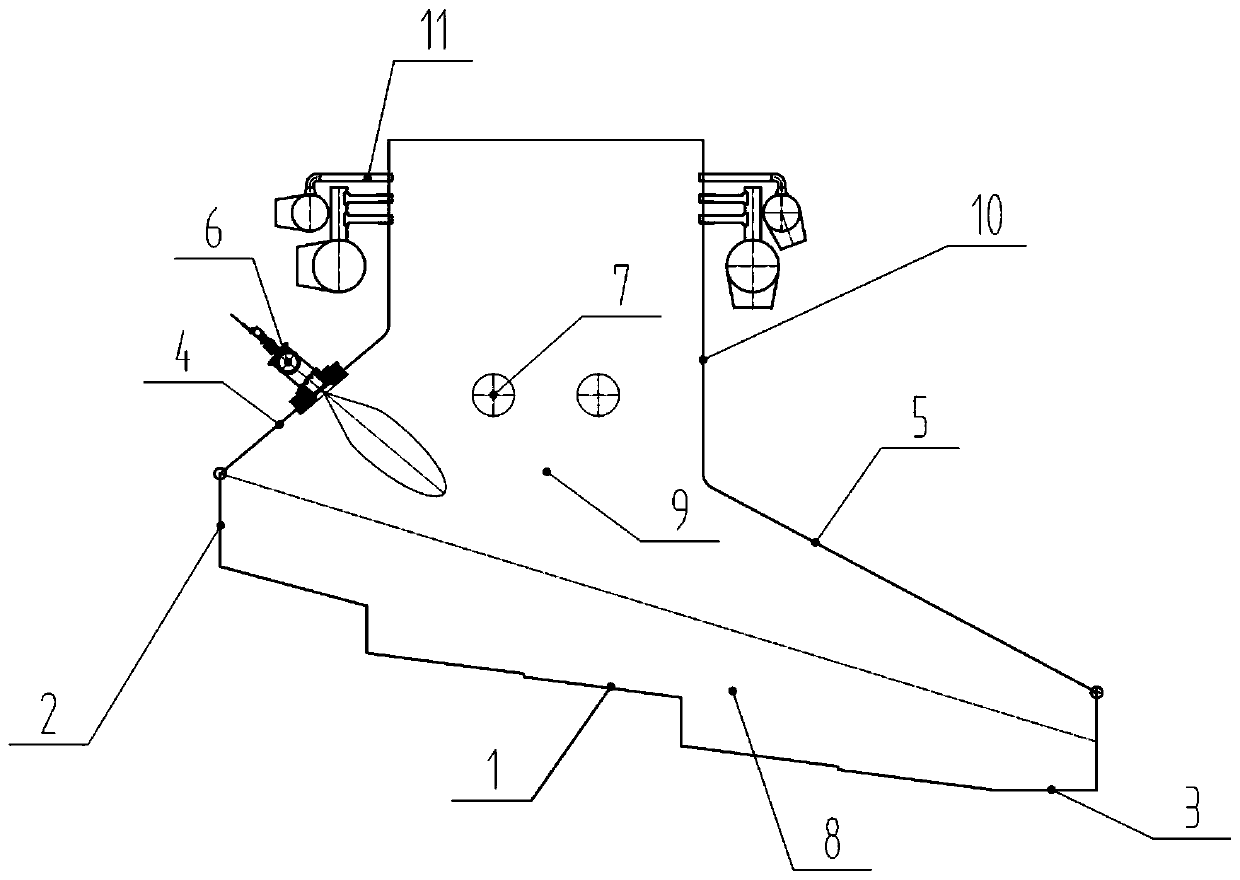
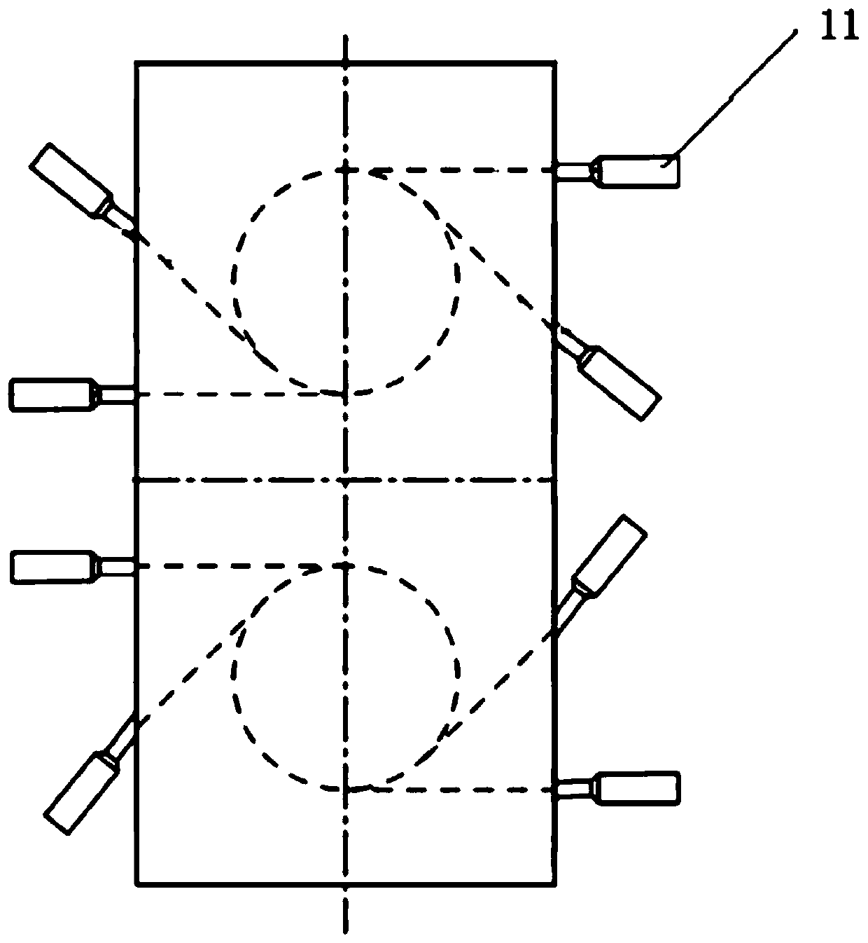
[0034] Furnace structure such as figure 1 As shown, the width of the hearth is 5.6 meters, the fire grate 1 is located at the bottom of the hearth, the front end is provided with a feed port 2, the tail end is provided with a slag discharge port 3, and both sides of the fire grate are refractory furnace walls 8. Two ignition burners 6 are arranged on the front arch 4 of the furnace wall on the upper part of the furnace, and an auxiliary burner 7 is respectively installed on the left and right side walls 9 . The entrance of the flue is located in the front middle of the furnace, the water wall is arranged around the flue 10, and extends to the middle of the furnace wall along with the front arch 4, the rear arch 5 and the side wall 9, and the lower part of the flue is provided with the entrance of the secondary air pipe 11, see figure 2 The diameter of the secondary wind shear circle is 3 meters. The angle α between the front buttress wall surface of the furnace and the horiz...

Embodiment 2

[0036] Same as embodiment 1, only the furnace width is 4.5 meters, the secondary wind cut circle diameter is 2.5 meters, the angle α between the wall of the front arch (4) of the furnace and the horizontal plane is 30 °, the angle between the wall of the rear arch of the furnace 5 and the horizontal plane β is 20°, the fire grate (1) is divided into four levels, and there is no water cooling wall at the front arch (4), rear arch (5) and side wall (9).

Embodiment 3

[0038] Same as embodiment 1, only the width of the hearth is set to 8 meters, the diameter of the secondary wind shear circle is 3.5 meters, the angle α between the 4 walls of the front arch of the hearth and the horizontal plane is 60°, and the angle β between the walls of the back arch 5 of the fire hearth and the horizontal plane is 50°, and there are three ignition burners (6).

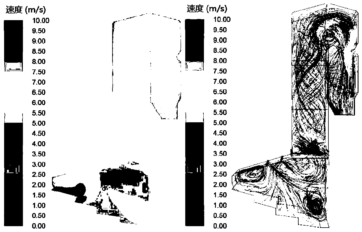
[0039] There is a 750t / d furnace type as attached image 3 As shown, the high temperature area generated by its combustion extends from the grate to the front arch of the furnace, and moves with the airflow to the direction of the flue. The secondary combustion occurs at the junction of the furnace and the flue, the temperature in the flue is low, and the combustion-supporting effect of the secondary air is limited. The temperature near the slag outlet is high, and the heat loss of slag discharge is relatively large. The overall flow velocity and disturbance degree of flue gas in the flue are lo...


PUM


Abstract

The invention relates to a novel 900-t/d high-heat-value domestic garbage incinerator. The incinerator is characterized in that a hearth is 4.5-8m in the width; the incinerator comprises a fire grate(1) at the bottom of the hearth, a feed inlet (2) at the front end, a slag outlet (3) at the tail end, fire-resistant furnace walls (8) at two sides of the fire grate, a hearth wall front arch (4) atthe upper part of the hearth, two ignition burners (6) at the upper part of the hearth; left and a right side walls (9), an auxiliary burner (7), a first flue inlet (10) at the front middle part of the hearth, a secondary air pipe (11) at the lower part of the first flue, and water-cooled walls arranged on the first flue (10), the front arch (4), a rear arch (5) and the side walls (9). The incinerator is suitable for the incineration treatment of high-heat value domestic garbage, and has the advantages of wide working condition adaptability, long service life of a boiler, low failure rate, high combustion efficiency, low pollutant discharge and the like.

Description

Technical field: [0001] Domestic waste incineration waste heat boiler. It is a boiler device that uses the high-temperature flue gas generated during the incineration of domestic waste to generate electricity. Background technique: [0002] In an existing 750t / d waste incinerator, the grate is a four-stage reciprocating grate, and the design calorific value of the fuel is 6800kJ / kg. The first channel, the second channel, the third channel, the horizontal fourth channel, the vertical fifth channel, and then enter the exhaust gas treatment system. As the calorific value of domestic waste has been increasing in recent years, the thermal load of the boiler has increased, coking on the furnace wall and tube bursts have occurred frequently, and the amount of waste treatment has decreased, which is not conducive to the smooth operation of the boiler. [0003] advantage: [0004] The reciprocating grate is adopted, and the vertical drop between the two levels of grate is relative...

Claims


Application Information

Patent Timeline
Patent Type & Authority Applications(China)
IPC IPC(8): F23G5/38F23G5/44F23J13/06F23L9/02
CPCF23G5/002F23G5/38F23G5/44F23J13/06F23L9/02
Inventor 张焕亨罗翠红吴荫津潘扬张钦华熊爱生刘文
Owner GUANGZHOU HUANTOU DESIGN & RES INST CO LTD
Why Eureka
Try Eureka