Microscopic heat distribution test method and system

A test method and heat distribution technology, applied in the field of microscopic heat distribution test methods and systems, can solve the problems of inaccurate test results, complicated test process, poor data and heat distribution image processing capabilities, etc.

Inactive Publication Date: 2019-04-09
广东金鉴实验室科技有限公司
View PDF2 Cites 1 Cited by
  • Summary
  • Abstract
  • Description
  • Claims
  • Application Information

AI Technical Summary

Problems solved by technology

However, the traditional heat distribution method and system have shortcomings such as overly complex detection process, inaccurate detection results,

Method used


Image

  • Microscopic heat distribution test method and system
  • Microscopic heat distribution test method and system

Examples


Embodiment

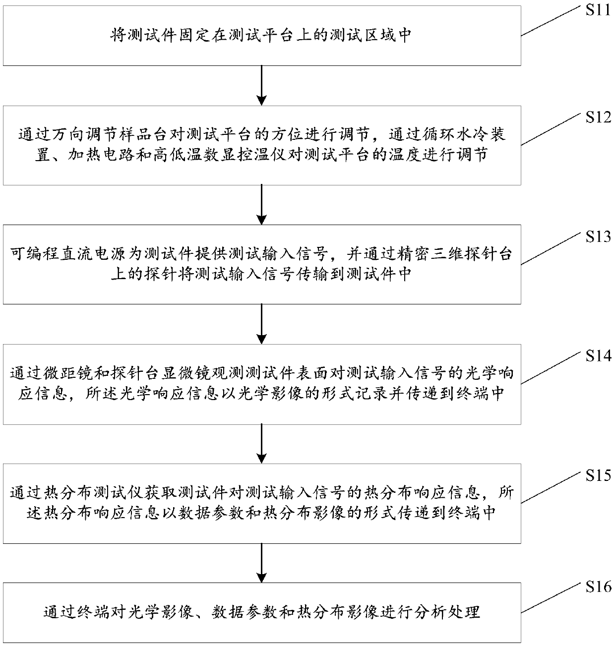
[0050] see figure 1 , figure 1 It is a schematic flow chart of a microscopic heat distribution testing method in an embodiment of the present invention.

[0051] like figure 1 Shown, a kind of microthermal distribution testing method, described method comprises:

[0052] S11: Fix the test piece in the test area on the test platform.

[0053] Specifically, the test platform is provided with a test area, and the surface of the test area is covered with a layer of magnets. When the test piece contains ferromagnetic substances such as iron, nickel, cobalt and other metals, the test area can attract the test piece so as to The test piece is fixed; in addition, the test platform is also provided with a test piece fixing device, when the test piece cannot be absorbed by the magnet on the surface of the test area or needs to be further fixed, the test piece can also be fixed by the test piece fixing device .

[0054] S12: Adjust the orientation of the test platform through the un...


PUM


Abstract

The invention discloses a micro heat distribution test method and system. The microscopic heat distribution test method comprises the following steps of: fixing the test piece on the test platform; adjusting the orientation of the test platform by the universal adjustment sample stage, and adjusting the temperature of the test platform by a circulating water cooling device, a heating circuit and ahigh and low temperature digital display temperature controller; transmitting the test input signal provided by the programmable DC power supply to the test piece through the probe; observing the optical response information from the surface of the test piece to the test input signal through a macro lens and a probe stage microscope, then recording and transmitting it in the form of an optical image to the terminal; obtaining the heat distribution response information of the test piece to the test input signal by the heat distribution tester, then transmitting it to the terminal in the form of data parameters and heat distribution images; and analyzing and processing optical images, data parameters, and thermal distribution images by the terminal. According to the microscopic heat distribution test method and system, the defect of the test piece can be accurately found by analyzing the heat distribution response information of the test piece.

Description

technical field [0001] The invention relates to the field of heat distribution testing, in particular to a microscopic heat distribution testing method and system. Background technique [0002] Due to the existence of black body radiation, any object radiates electromagnetic waves according to different temperatures, and the part with a wavelength of 2.0 to 1000 microns is called thermal infrared. Thermal infrared imaging uses thermal infrared to image objects, which can reflect the temperature field on the surface of the object. Among them, the principle of thermal infrared imaging has been widely used in military, industrial, automotive assisted driving, and medical fields. [0003] In recent years, the principle of thermal infrared imaging has been widely used in the industrial field. Manufacturers use the principle of thermal infrared imaging to detect defects in electronic components, and the detection effect has been generally recognized. However, the traditional the...

Claims


Application Information

Patent Timeline
IPC IPC(8): G01J5/00
CPCG01J5/00G01J5/485
Inventor 方方林凯旋邱岳
Owner 广东金鉴实验室科技有限公司
Why Eureka
Try Eureka