Hollow cathode heater and hollow cathode structure

A hollow cathode and heater technology, applied in the direction of the hollow cathode of the discharge tube, the main electrode of the discharge tube, the machine/engine, etc., can solve the problems such as the thermal shock of the heating wire and the reduction of the thermal efficiency, which can improve the reliability and service life. Reduce thermal shock, good reliability

Active Publication Date: 2019-04-09
SHANGHAI INST OF SPACE PROPULSION
View PDF6 Cites 12 Cited by
  • Summary
  • Abstract
  • Description
  • Claims
  • Application Information

AI Technical Summary

Problems solved by technology

Although this technology has improved the reliability of the hollow cathode heater to a certain extent, it still cannot solve the thermal shock to the heating wire caused by the induced magnetic field at the instant of ignition, and the thermal efficiency reduction caused by the external heat conduction and heat radiation of the heater. There is still room for improvement in the performance of hollow cathode heaters

Method used


Image

  • Hollow cathode heater and hollow cathode structure
  • Hollow cathode heater and hollow cathode structure
  • Hollow cathode heater and hollow cathode structure

Examples


Embodiment 1

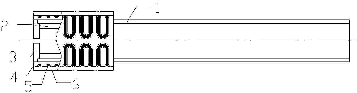
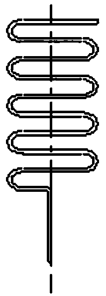
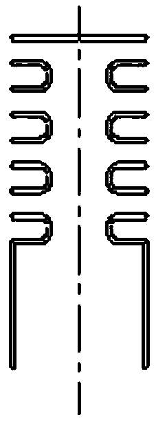
[0051] like Figure 5 and Image 6The two parts a and b of the inner ceramic skeleton 4 are shown respectively, and there are serpentine spiral grooves meandering parallel to the direction of the ceramic axis, and the threads of the part a of the inner ceramic skeleton 4 and the part b of the inner ceramic skeleton 4 are symmetrical to each other . use as figure 2 and image 3 In the first winding method shown, the heating wire 5 is wound along the serpentine spiral grooves on the outer surface of part a and part b of the inner ceramic skeleton 4, and two parts of the heating wire 5 are wound into the inner ceramic skeleton 4 The outer surface position of the heating wire 5 is welded, and the unwelded two ends of the heating wire 5 are respectively connected to the heating positive electrode and the heating negative electrode, and the two parts of the heating wire 5 form a series structure.

[0052] For the serpentine heating wire, the induced magnetic fields at adjacent ...

Embodiment 2

[0054] Embodiment 2 is consistent with Embodiment 1 in that: the inner ceramic skeleton 4 is divided into two parts a and b, and has a serpentine spiral groove parallel to the direction of the ceramic axis. figure 2 and image 3 In the first winding method shown, the heating wire 5 is wound along the serpentine spiral grooves on the outer surface of part a and part b of the inner ceramic skeleton 4; the difference from embodiment 1 is that after the winding is completed, The terminals of the two parts of the heating wire 5 on the top are connected together and then welded on the cathode tube to connect to the negative electrode; the terminals of the two parts of the heating wire 5 at the other end of the inner ceramic skeleton 4 are connected together and connected to the heating positive electrode, and the two heating wires are connected in parallel structure.

[0055] It is also a serpentine heating wire, the current direction of adjacent positions is opposite, and the ind...

Embodiment 3

[0057] like Figure 7 , Figure 8 as well as Figure 9 As shown, the one-piece inner ceramic skeleton 4 distributes protrusions in an array in a direction parallel to the ceramic axis, as shown in Figure 10 As shown, the heating wire 5 is reciprocally wound along the convex part of the inner ceramic skeleton. The two ends of the heating wire 5 are respectively connected to the heating positive electrode and the heating negative electrode without welding. Due to the difficulty of welding and fixing near the top of the cathode tube, and the hollow cathode discharge plasma sputtering is easy to be eroded, and the influence of high temperature on welding reliability, the heater is disconnected due to falling off. This structure saves the welding between the heating wire and the cathode tube, reduces the processing difficulty and improves the reliability.

[0058] At the same time, with the serpentine heating wire, the induced magnetic fields at adjacent positions can cancel e...


PUM


Abstract

The present invention discloses a hollow cathode heater and a hollow cathode structure, the heater comprises an inner ceramic skeleton (4), a heating wire (5) and an outer ceramic sleeve (6); outer side of the inner ceramic skeleton (4) and/or inner side of the outer ceramic sleeve (6) has a first a structure; the first structure is any one or any combination of a protrusion, a groove or a smoothsurface; the outer ceramic sleeve (6) is nested outside the inner ceramic skeleton (4), a first space is surrounded and formed between the outer side of the inner ceramic skeleton (4) and the inner side of the outer ceramic sleeve (6) through the first structure. The hollow cathode heater is easy to process and assemble, has high mechanical strength and high reliability, and has a serpentine heating wire, with induced magnetic fields at adjacent positions cancelling each other, can effectively reduce an induced voltage and an induced current generated by the induced magnetic fields at the ignition moment, reduce thermal shock of the heating wire and improve reliability and life span of a space electric propulsion system.

Description

technical field [0001] The present invention relates to the field of aerospace propulsion technology, in particular, to a hollow cathode heater and a hollow cathode structure, especially a hollow cathode heater structure that can be used in fields such as electric propulsion and can offset electromagnetic induction, preferably a New snake-shaped hollow cathode heater structure. Background technique [0002] Hollow cathodes are widely used, not only in plasma discharge-related fields, such as surface treatment, vacuum coating, vacuum welding, etc., but also as electron sources and neutralizers in aerospace electric propulsion systems, known as vacuum electrons. The "heart" of the device. When applied to an electric propulsion system, the hollow cathode is one of the core components of the system, and its various performances are important indicators that limit the performance of the thruster. Since the hollow cathode bears the highest plasma density, the highest current den...

Claims


Application Information

Patent Timeline
Patent Type & Authority Applications(China)
IPC IPC(8): H01J1/02F03H1/00
CPCF03H1/0031H01J1/025
Inventor 乔彩霞王亚楠康小录张岩张志远王仲远余水淋杭观荣程佳兵李林赵震贾晴晴
Owner SHANGHAI INST OF SPACE PROPULSION
Why Eureka
Try Eureka