Coil grouping method for stator module combined motor

A coil grouping and combination technology, which is applied in the direction of prefabricated windings embedded in motors, manufacturing of motor generators, electrical components, etc., can solve the problems of difficult maintenance, difficult disassembly and maintenance of motors, large vibration and noise, etc., and achieve the effect of mechanical decoupling.

Inactive Publication Date: 2019-04-09
SHENYANG POLYTECHNIC UNIV
View PDF7 Cites 0 Cited by
  • Summary
  • Abstract
  • Description
  • Claims
  • Application Information

AI Technical Summary

Problems solved by technology

In the traditional asynchronous motor acceleration and deceleration drive mode, the efficiency and power factor of the asynchronous motor are low, and the gear reducer equipment makes the transmission structure complex, low efficiency, and large vibration and noise, so the low-speed high-torque permanent magnet motor direct drive mode is widely used
However, the wire rope reel is coaxially connected with the motor rotor, and the force on the reel is not uniform in actual work, so it is difficult to control the constant air gap of the motor
In 2013, Dalian Burton Guanli Motor Co., Ltd. applied for utility model patents "a built-in outer rotor permanent magnet motor direct drive mine hoist (patent number: 20131096130.2)", "a kind of outer rotor permanent magnet motor direct drive integration Mine Hoist (Patent No.: 201310232074.3)", which avoids the problems of uneven force on the suspended rotor structure and difficult control of the motor air gap
However, there are problems in the application of low-speed and high-torque external rotor permanent magnet motor integrated design in mine hoists, heavy cranes, winches and other fields: due to the existence of transmission structures such as drums, wire ropes, and hoisting containers in hoisting devices, Difficult to disassemble and maintain the motor
It solves the problems of manufacturing, transportation, assembly and maintenance difficulties caused by the large size of the motor
However, the coils adopt unequal spans and reverse embedding methods to make the parameters of the three-phase windings asymmetrical.
In 2014, CSR Zhuzhou Electric Co., Ltd. applied for a utility model patent "a direct drive permanent magnet wind turbine with a double stator split structure (patent number: 201420672300.X)". The split stators are all equipped with complete U, V, and W three-phase coils, but there is no specific description of the method to realize that each lobe is equipped with complete U, V, and W three-phase coils

Method used


Image

  • Coil grouping method for stator module combined motor
  • Coil grouping method for stator module combined motor
  • Coil grouping method for stator module combined motor

Examples


Embodiment Construction

[0018] Below in conjunction with accompanying drawing, the present invention will be further described:

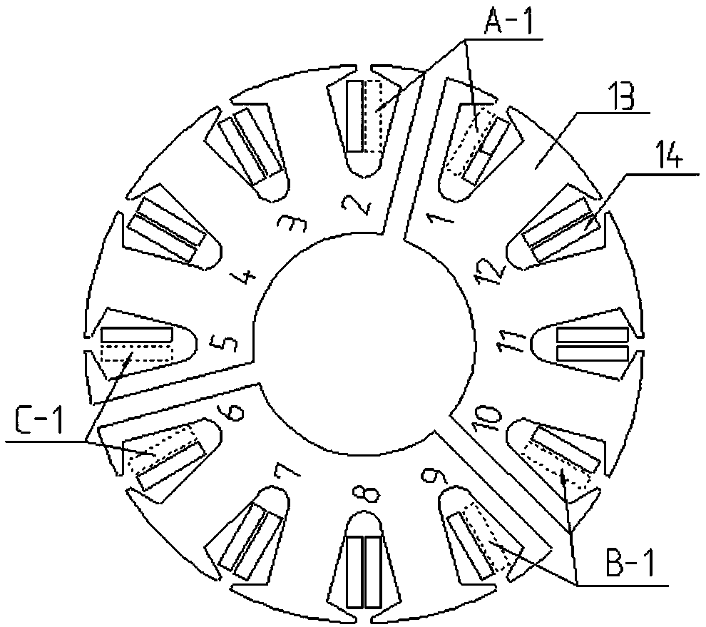
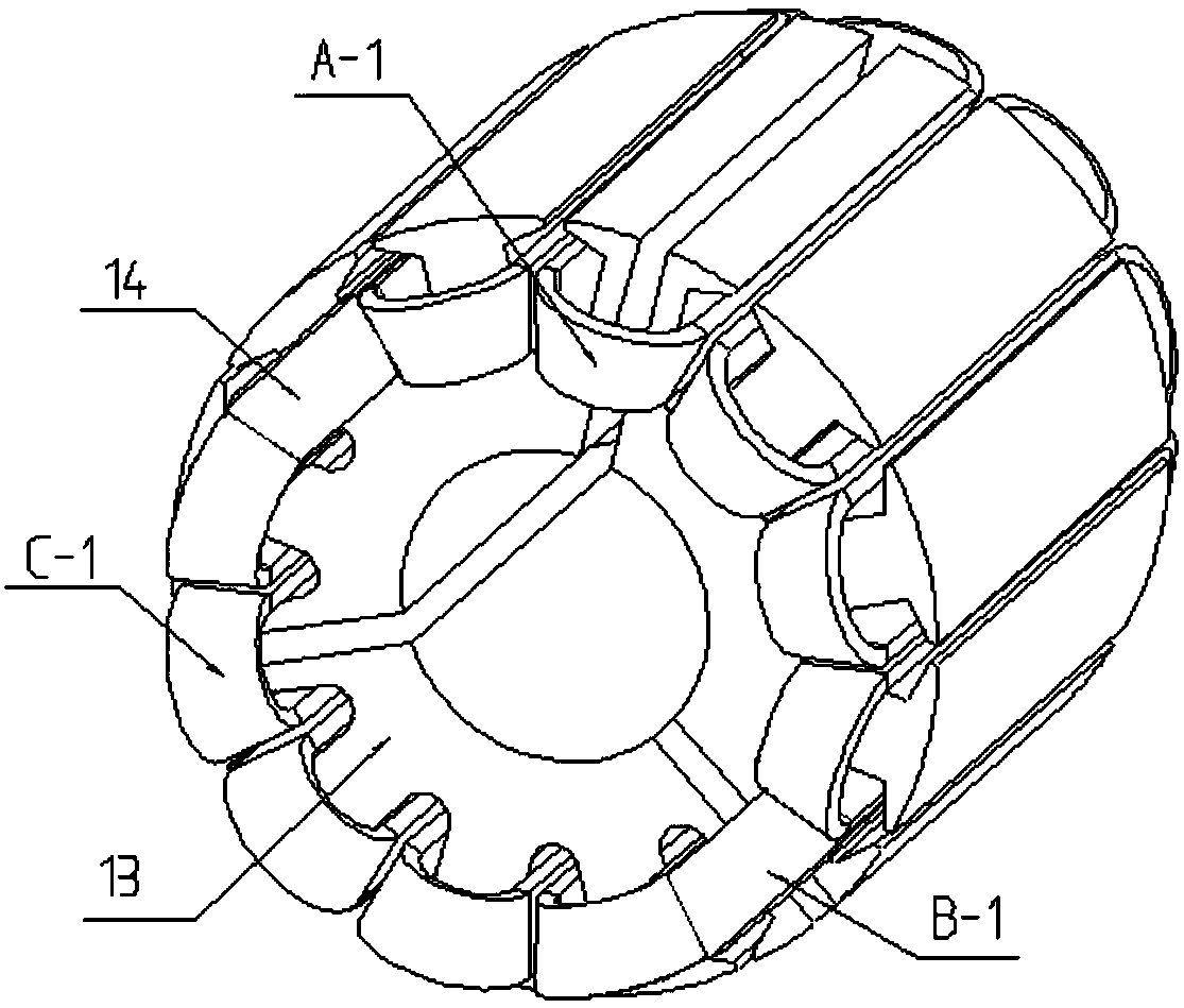
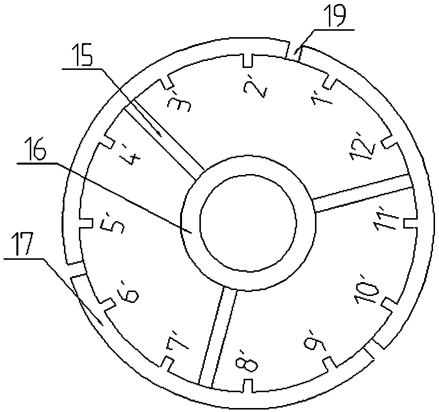
[0019] Such as figure 1 with figure 2 As shown, this embodiment takes a unit motor with 10 poles and 12 slots as an example for illustration. The stator core 13 is laminated by punched sheets, and the end is pressed by a stator pressure ring. Twelve stator slots are evenly opened on the outer circumference of the stator core 13, and the coil 14 is inserted into the stator slot according to the rule of straddling one stator tooth. The number of motor stator slots is Q 1 , the number of module slots according to a single stator block is Q 0 = Q 1 The rule of / s is divided into equal blocks, Q 0 must also satisfy Q 0 =12*(n / 6+k), where n =1, 2, 4 or 5, k=0, 1, 2 or 3.......Natural number, the number of stator blocks is s, s is The law of 3 or integer multiples of 3. This embodiment Q 1 =12, s=3, Q 0 =12 / 3=4, 4=12*(2 / 6+0), n=2, k=0, conforming to n =1, 2, 4 or 5, k=0...


PUM


Abstract

The invention belongs to the technical field of motors, and relates to a coil grouping method for a stator module combined motor. Stator slots are uniformly formed in the periphery of a stator core, acoil is embedded into the stator slots according to the law of spanning one stator tooth, the number of the stator slots of the motor is Q1, equal partitioning is performed according to the rule thatthe number of module slots of a single stator sub-block is Q0=Q1/s, Q0 must also satisfy Q0=12*(n/6+k), wherein n=1, 2, 4 or 5, k=natural numbers 0, 1, 2 or 3..., the number of stator sub-blocks is s, s is 3 or integral multiples of 3, the coils that are embedded across the teeth are removed at the stator sub-blocks, and partitioning is performed at the center line of the tooth part after the coil is removed. The scheme of the invention brings convenience to the stator module combination, and solves the problem of cutting dispersion by innovatively using a fixed cylinder.

Description

technical field [0001] The invention belongs to the technical field of motors, and relates to a coil grouping method of a stator module combined motor used in large permanent magnet motor equipment in a high-power, high-torque direct drive system. Background technique [0002] With the continuous development and improvement of motor technology, motor technology is playing an increasingly important role in promoting the development of the national economy. In the traditional asynchronous motor acceleration and deceleration drive mode, the efficiency and power factor of the asynchronous motor are low, and the gear reducer equipment makes the transmission structure complex, low efficiency, and large vibration and noise. Therefore, the direct drive mode of low-speed high-torque permanent magnet motor is widely used. However, the wire rope reel is coaxially connected with the motor rotor, and the force on the reel is not uniform in actual work, so it is difficult to control the c...

Claims


Application Information

Patent Timeline
Patent Type & Authority Applications(China)
IPC IPC(8): H02K1/18H02K1/14H02K15/06
CPCH02K1/14H02K1/18H02K15/062H02K2201/15H02K2213/03
Inventor 张炳义徐莹莹冯桂宏吴青松
Owner SHENYANG POLYTECHNIC UNIV
Why Eureka
Try Eureka