
A spiral vertical farm with rotatable belt operating device
A technology of operating device and rotary drive device, which is applied in the direction of lifting device, fertilization device, automatic watering device, etc., can solve the problems of not being able to receive sunlight continuously and being fixed, so as to save time, energy and labor, and rotate the drum Smooth, energy-reducing effect
- Summary
- Abstract
- Description
- Claims
- Application Information
AI Technical Summary
Problems solved by technology
Method used
Image

Examples
Embodiment 1
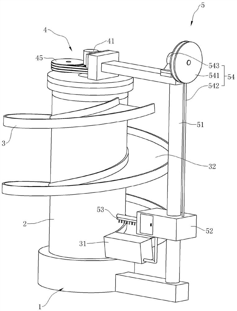
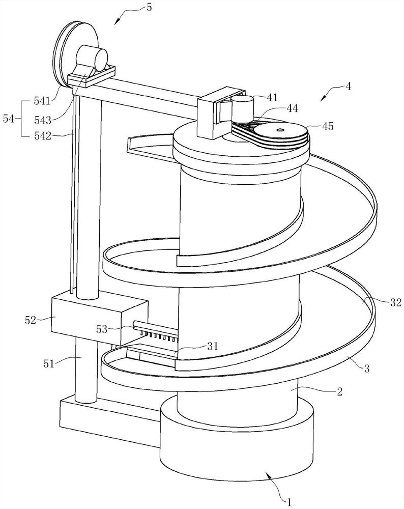
[0030] A kind of spiral vertical farm with rotatable belt operating device provided in this embodiment, such as figure 1 As shown, it includes a base 1, a rotating drum 2, a spiral planting platform 3 and a rotary drive device 4. The rotating drum 2 is vertically supported and arranged above the base 1, and the spiral planting platform 3 is helically wound and fixedly connected to the outer wall of the rotating drum 2. , the spiral planting platform 3 is used for planting plants, and the rotary drive device 4 is connected to the rotary drum 2 to drive the rotation, so that different positions of the spiral planting platform 3 receive sunlight in turn, and the radiation intensity received by plants at different positions more evenly.
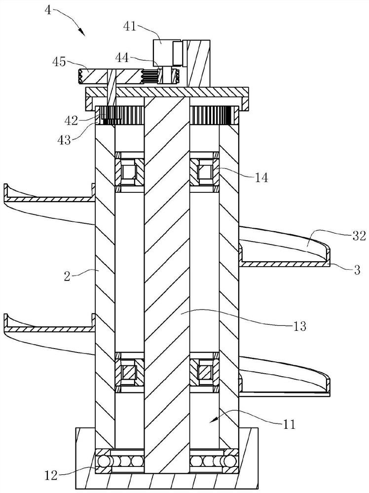
[0031] combine figure 2 , the upper surface of base 1 is provided with accommodating groove 11, and a thrust bearing 12 is arranged in accommodating groove 11, and the bottom end of drum 2 is inserted in accommodating groove 11, and the upper e...
Embodiment 2
[0039] This embodiment provides a spiral vertical farm with a rotatable belt operating device. The difference from Embodiment 1 is that, as Figure 4 As shown, the rotary drive device 4 is located at the bottom of the drum 2, the rotary drive device 4 includes a rotary drive motor 41 and a rotary transmission mechanism, the rotary drive motor 41 is fixedly connected to the base 1, and the rotary transmission mechanism includes a driving gear 42 and a driven gear 43, the driving gear 42 meshes with the driven gear 43, the driving gear 42 is connected to the output shaft of the rotary drive motor 41, the driven gear 43 is fixedly connected to the drum 2, and the rotation center axis of the driven gear 43 is connected to the rotating drum 2. The central axis coincides.
Embodiment 3
[0041] This embodiment provides a spiral vertical farm with a rotatable belt operation device. The difference from Embodiment 2 is that, as Figure 5 As shown, the base material distribution device 5 also includes a surrounding drive device 55, the surrounding driving device 55 includes a surrounding driving motor 551, a surrounding main gear 552, a surrounding secondary gear 553 and an annular turntable 554, and the surrounding driving motor 551 is fixedly connected to the base 1, The surrounding main gear 552 is fixedly connected with the output shaft of the surrounding driving motor 551, the annular turntable 554 is connected with the base 1 for horizontal rotation, the rotating cylinder is located inside the annular turntable 554, the column 51 is fixedly connected with the annular turntable 554, and the surrounding slave gear 553 is connected with the annular turntable 554 is fixedly connected, encircling the main gear 552 and encircling the slave gear 553 to mesh. When t...
PUM
 Abstract
Description
Claims
Application Information