Optical fiber and method for fabricating the same

a technology of optical fiber and fiber, applied in the field of optical fiber and methods for fabricating the same, can solve the problems of inability to obtain sufficient uniform light intensity, inability to break optical fiber, and inability to manufacture optical fiber

Active Publication Date: 2010-11-04
MITSUBISHI CABLE IND LTD
View PDF5 Cites 14 Cited by
  • Summary
  • Abstract
  • Description
  • Claims
  • Application Information

AI Technical Summary

Benefits of technology

[0018]According to the present invention, an optical fiber includes a core having a rectangular cross section and made of quartz, and a cladding surrounding the core, having a circular outer cross-sectional shape, and made of resin. This can provide an optical fiber from which a laser beam with uniform irradiation intensities is emitted.

Problems solved by technology

However, since this mode scrambling requires the winding of an optical fiber, the optical fiber may be broken, and the size of a mode scrambling device (mode scrambler) may increase.
In addition, sufficiently uniform light intensities cannot be obtained by merely winding an optical fiber having a length of hundreds of meters.
This decreases processing efficiency.

Method used


Image

  • Optical fiber and method for fabricating the same
  • Optical fiber and method for fabricating the same
  • Optical fiber and method for fabricating the same

Examples


first embodiment

of the Invention

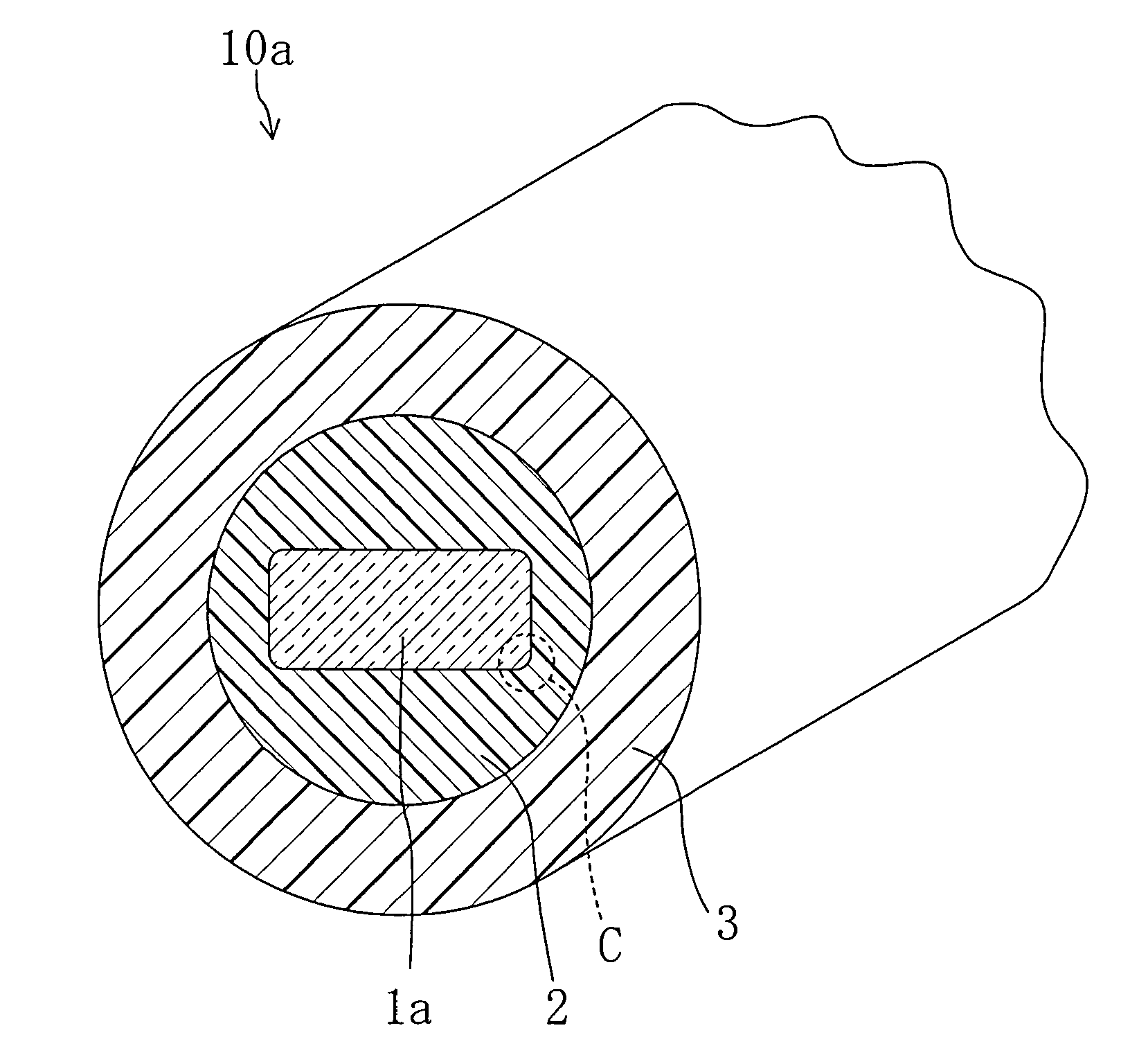
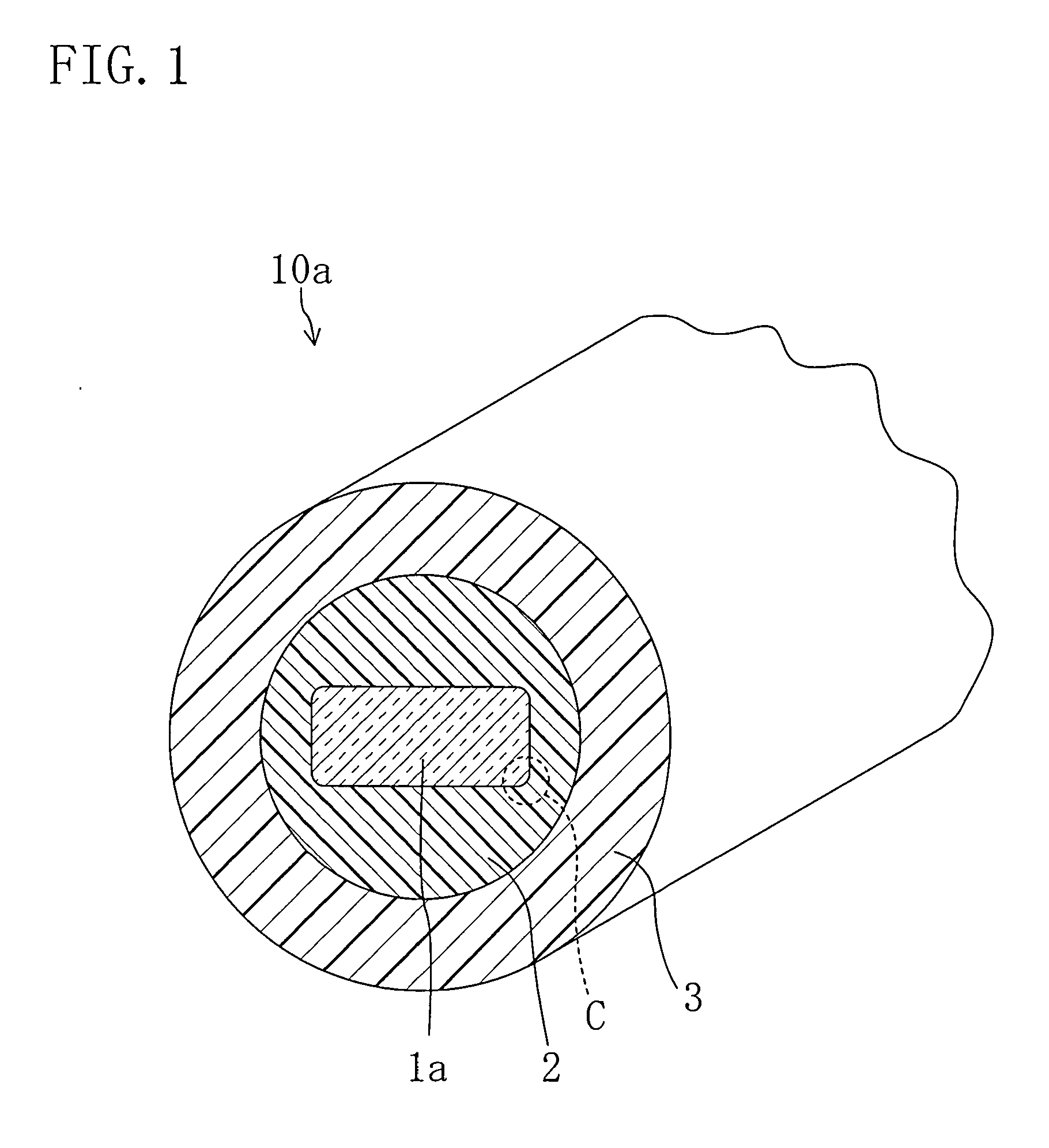
[0033]FIGS. 1-5 illustrate an optical fiber according to a first embodiment of the present invention and a method for fabricating the same. Specifically, FIG. 1 is a perspective view illustrating an optical fiber 10a of this embodiment.

[0034]As illustrated in FIG. 1, the optical fiber 10a includes a centrally located core 1a having an oblong rectangular cross section, a cladding 2 surrounding the core 1a and having a circular outer cross-sectional shape, and a cylindrical protection layer 3 surrounding the cladding 2.

[0035]The core 1a is made of quartz, and the corners C of the oblong rectangular cross section of the core la each have a radius of curvature of 1 / 100- 1 / 10 of the length of a long side of the oblong rectangle.

[0036]The cladding 2 is made of, e.g., a thermosetting silicone resin, and has a lower refractive index (e.g., 1.408) than the core 1a (made of pure quartz).

[0037]The protection layer 3 is made of, e.g., polyamide resin, and is provided to protect ...

second embodiment

of the Invention

[0054]FIG. 6 is a perspective view of an optical fiber 10b of this embodiment. In the following embodiment, the same reference characters as those in FIGS. 1-5 are used to represent equivalent elements, and the detailed explanation thereof will be omitted.

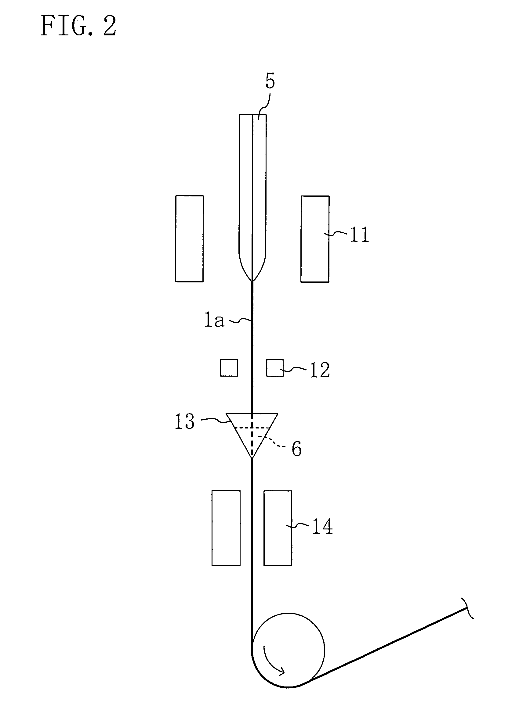
[0055]Although the optical fiber 10a of the first embodiment includes the core 1a having an oblong rectangular cross section, the optical fiber 10b of this embodiment includes a core 1b having a square cross section. Here, the core 1b can be formed by changing the shape of the core material 5 used in the core formation process step of the first embodiment. Specifically, the core 1b is formed under the following conditions: the dimensions of a core material (5) are approximately 20 mm high by 20 mm wide by 200 mm long; the temperature of a drawing furnace 11 is 2020° C.; and the drawing speed of the core 1b is 8 m / min. The optical fiber 10b can be fabricated which includes the core 1b having a square cross section wi...


PUM

PropertyMeasurementUnit
temperatureaaaaaaaaaa
speedaaaaaaaaaa
lengthaaaaaaaaaa

Abstract

An optical fiber includes a core (1a) having an oblong rectangular or square cross section and made of quartz, and a cladding (2) surrounding the core (1a), having a circular outer cross-sectional shape, and made of resin.

Description

TECHNICAL FIELD[0001]The present invention relates to optical fibers and methods for fabricating the same, and more particularly relates to an optical fiber for a laser guide used to transmit laser beams, and a method for fabricating the same.BACKGROUND ART[0002]Laser guides have been widely used, as optical fiber components for transmitting laser beams with high energy density, for machining equipment, etc.[0003]Incidentally, laser machining for a surface ablation process for semiconductor, etc., using a laser beam emitted through a laser guide requires that the intensities of a laser beam at the spot irradiated with the laser beam be uniform.[0004]A conventional optical fiber including, e.g., a core having a circular cross section, and a cladding surrounding the core is configured such that the distribution of the intensities of a laser beam at the spot irradiated with the laser beam corresponds to a Gaussian distribution. Therefore, in order to obtain uniform intensities of the l...

Claims


Application Information

Patent Timeline
Patent Type & Authority Applications(United States)
IPC IPC(8): G02B6/02G02B6/00C03B37/025C03C25/10
CPCC03C25/105G02B6/4296G02B6/02033
Inventor NAKAI, TADAHIKOKINOSHITA, TAKAHARUSATAKE, TAKESHIAKUTSU, TAKEJIYAMASAKI, MOTOHIKO
Owner MITSUBISHI CABLE IND LTD
Why Eureka
Try Eureka