Lock cylinder installing machine

A lock cylinder and rack technology, applied in the field of lock assembly equipment, can solve the problems of shell errors, affecting product qualification rate, and time-consuming and other problems

Active Publication Date: 2019-04-12
永嘉县信达智能设备制造有限公司
View PDF4 Cites 3 Cited by
  • Summary
  • Abstract
  • Description
  • Claims
  • Application Information

AI Technical Summary

Problems solved by technology

[0003] Existing lock cylinders are generally operated manually. The operator can judge by himself to put the warhead of suitable size into the lock case, and then put the flat head, spring and sealing beads in sequence. The above process must be repeated for each keyhole, which is time-consuming. Laborious, high error rate
[0004] Of course, there are also very few automated assembly machines, but their clamping devic

Method used


Image

  • Lock cylinder installing machine
  • Lock cylinder installing machine
  • Lock cylinder installing machine

Examples


Embodiment Construction

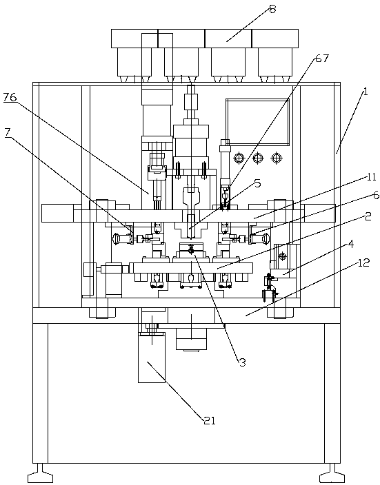
[0131] Embodiments of the present invention will be further described below in conjunction with accompanying drawings:

[0132] As shown in the figure, a lock cylinder installation machine includes:

[0133] Frame 1 is provided with an ingot rack 11 and a stand 12 installed from top to bottom;

[0134] A rotary table 2, which is installed on the platform 12 and is provided with a driving device 21 that can drive it to rotate and a plurality of clamping devices 3 arranged along the circumferential direction;

[0135] Tooth stain reading device 4, which is installed on a corner of the stand 12;

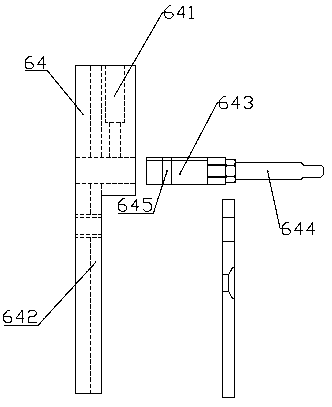
[0136] The positioning mechanism 5, the warhead flat head loading device 6 and the spring bead loading device 7 are fixedly installed on the ingot rack 11 in sequence, and all correspond to the clamping device 3 below;

[0137] The feeding device 8 is fixedly installed on the upper end of the frame 1 and communicates with the warhead flat head loading device 6 and the spring bead load...


PUM


Abstract

The invention discloses a lock cylinder installing machine, and relates to a lock assembly device. The lock cylinder installing machine comprises a rack, a rotary work table, a positioning mechanism,a marble and flat head loading-in device and a spring and sealing bead loading-in device; the rack is internally provided with a shoe-shaped gold ingot support and a table support; the rotary work table is mounted on the table support and is provided with a driving device capable of driving the rotary work table and a plurality of clamping devices arranged in the circumferential direction; the positioning mechanism, the marble and flat head loading-in device and the spring and sealing bead loading-in device are fixedly mounted on the shoe-shaped gold ingot support in sequence to correspond theclamping devices below; and each clamping device has a first state in which a lock cylinder is fixed after positioning by the positioning mechanism, a second state in which a marble and a flat head are loaded into the lock cylinder through the marble flat head loading device and a third state in which a spring and a sealing bead are installed in the lock cylinder through the spring bead sealing loading-in device. The lock cylinder installing machine has the advantages of the high automation degree, the high processing efficiency and the good processing precision.

Description

technical field [0001] The invention relates to lock assembly equipment, in particular to a lock cylinder assembly machine. Background technique [0002] The lock cylinder of the handle lock is generally as follows: Figure 24 As shown, the assembly of the lock cylinder (S1) needs to install the bullet (S2), flat head (S3), spring (S4) and sealing bead (S5) into the lock hole (S6) of the lock cylinder from bottom to top in sequence, and the lock The holes are arranged linearly. There are many sizes of bullets corresponding to the groove pattern on the key. The flat head, spring and sealing bead all have only one size. Therefore, it is necessary to install bullets of appropriate size in specific lock holes during installation. [0003] Existing lock cylinders are generally operated manually. The operator can judge by himself to put the warhead of suitable size into the lock case, and then put the flat head, spring and sealing beads in sequence. The above process must be repea...

Claims


Application Information

Patent Timeline
IPC IPC(8): B23P21/00B23P19/00E05B17/00
CPCB23P19/001B23P21/006E05B17/0004
Inventor 潘州州
Owner 永嘉县信达智能设备制造有限公司
Why Eureka
Try Eureka