Electric automobile head energy recovery device based on stamping utilization

An energy recovery device and electric vehicle technology, applied in the automotive field, can solve problems such as high cost, unsuitable use requirements, and small size, and achieve the effects of stabilizing the internal flow field, reducing impact pressure, and reducing energy loss

Inactive Publication Date: 2019-04-12
HARBIN ENG UNIV
View PDF5 Cites 1 Cited by
  • Summary
  • Abstract
  • Description
  • Claims
  • Application Information

AI Technical Summary

Problems solved by technology

But the disadvantage is that the cost of this product is high, the size is small, and it does not meet the needs of people's daily use.

Method used


Image

  • Electric automobile head energy recovery device based on stamping utilization
  • Electric automobile head energy recovery device based on stamping utilization
  • Electric automobile head energy recovery device based on stamping utilization

Examples


Embodiment 1

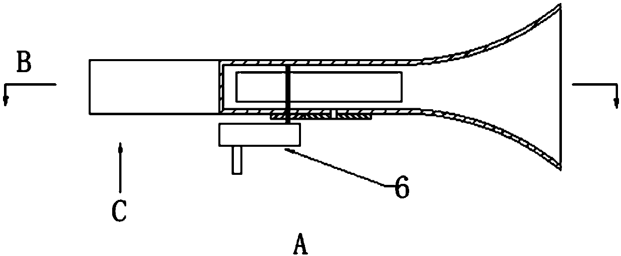
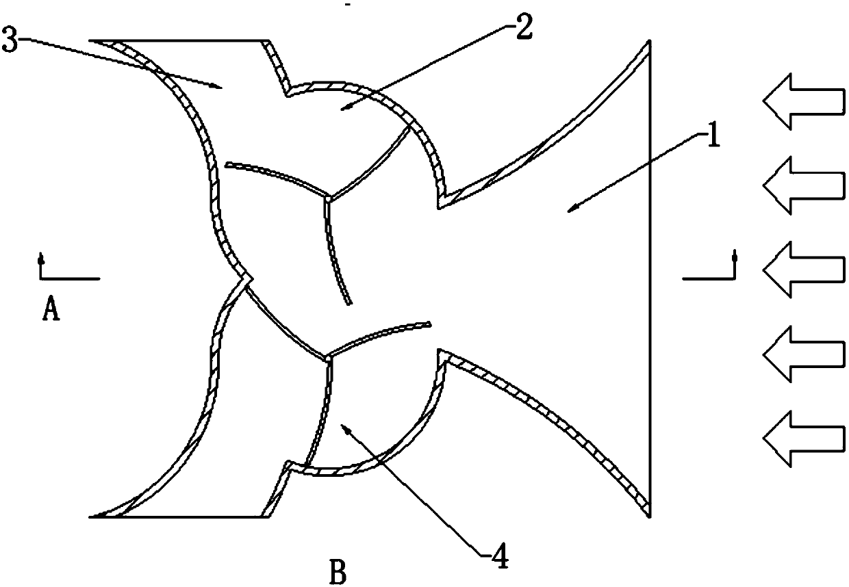
[0021] An energy recovery device for the front of an electric vehicle based on stamping utilization. Its structure includes an inlet section 1, an outlet section 3, a fan 4, a gear structure 5, and a reducer 6. The front end opens to the openings on both sides of the rear end of the front end. The inlet section 1 is connected to the outlet section 3 through the impact section 2. The impact section 2 has the fan 4 built in. Below the impact section 2, the fans 4 are connected in sequence The gear structure 5 and the reducer 6.

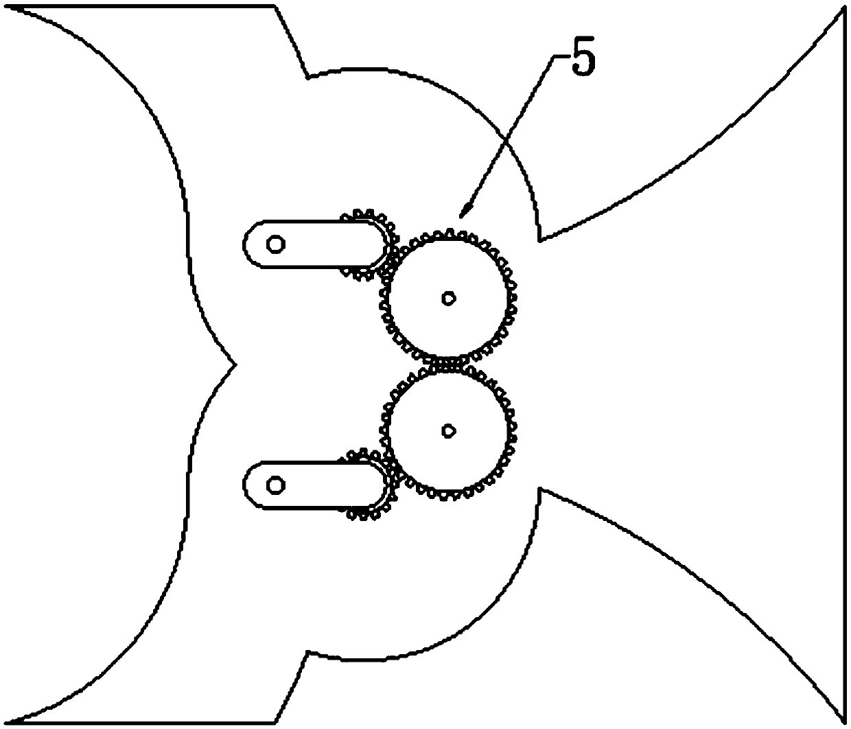
[0022] The number of the fans 4 is two, placed symmetrically to the axis of symmetry of the car in the impact section, and the blades are kept engaged, the shafts of the fans are perpendicular to the ground, the distance between the shafts of the two fans is less than the diameter of the fans, and the fans are run-off Type three-blade fan, the fan blades are concave and have no corners.

[0023] The flow channel of the inlet section 1 has a rectangular...

Embodiment 2

[0029] The purpose of the present invention is to reduce the air resistance when the electric vehicle is running, reduce the overall energy consumption, recover the wind impact pressure energy of the front of the vehicle and convert it into electric energy, prolong the battery life of the electric vehicle, save energy and reduce emission.

[0030] The purpose of the present invention is achieved like this:

[0031] An electric vehicle front energy recovery device based on stamping utilization includes an inlet section, an impact section, an outlet section, a fan, a gear structure and a reducer. The device is located at the front of the electric vehicle and is symmetrical about the symmetry axis of the vehicle. From the opening at the front end of the front end to the openings on both sides of the rear end of the front end, it connects the entrance section, the impact section and the exit section in sequence. Two fans are built in the impact section, and the fan shaft passes thr...


PUM


Abstract

The invention discloses an electric automobile head energy recovery device based on stamping utilization, and belongs to the field of automobiles. The structure of the device comprises an inlet section 1, an outlet section 3, a fan 4, a gear structure 5 and a speed reducer 6, wherein the device is positioned at the automobile head, forms symmetry relative to the symmetry axis of an automobile, andcomprises an opening in the foremost end of the head and openings in the two sides of the rear end of the head; the inlet section 1 is connected with the outlet section 3 through an impact section 2;the fan is arranged in the impact section 2; the shaft of the fan 4 below the impact section 2 is sequentially connected with the gear structure 5 and the speed reducer 6. The device reduces air dragto the electric automobile during driving, reduces the overall energy consumption, recovers head wind impact pressure energy and converts the energy into electric energy, prolongs the endurance of the electric automobile, saves energy and reduces emission, can furthest reduce energy loss, forms symmetry relative to the symmetry axis of the electric automobile, ensures that the internal flow fieldof the electric automobile is stable when the electric automobile is driven at a high speed, and ensures that problems, such as trackslip and lateral stress imbalance of the electric automobile caused by pneumatic reason cannot occur.

Description

technical field [0001] The invention belongs to the field of automobiles, and in particular relates to an energy recovery device for the front of an electric vehicle based on stamping utilization. Background technique [0002] Based on relevant statistics, it can be seen that the sales volume of electric vehicles is not large. After analysis, due to the large power consumption of electric vehicles, small storage capacity, and unsound infrastructure such as charging piles, the battery life of electric vehicles has become a matter of great concern to people. How to reduce the energy consumption of electric vehicles and increase the battery life of electric vehicles has become a research hotspot in various countries. [0003] At present, how to capture the high-speed airflow around the car has become one of the research focuses at home and abroad. The field of wind energy vehicles in my country is still in the theoretical research stage, the most notable is the invention paten...

Claims


Application Information

Patent Timeline
IPC IPC(8): B60L8/00F03D9/32
CPCB60L8/006F03D9/32Y02E10/72Y02E10/728Y02T10/7072
Inventor 栾一刚符昊殷越孙海鸥王松程享
Owner HARBIN ENG UNIV
Why Eureka
Try Eureka