

Coal conveying device
A conveying device and conveying pipeline technology, which is applied in the field of conveying machinery to achieve the effect of reducing accumulation and preventing coal clogging
- Summary
- Abstract
- Description
- Claims
- Application Information
AI Technical Summary
Problems solved by technology
Method used
Image

Examples
Embodiment Construction
[0020] The present invention will be described in detail in conjunction with accompanying drawing now. This figure is a simplified schematic diagram only illustrating the basic structure of the present invention in a schematic manner, so it only shows the components relevant to the present invention.
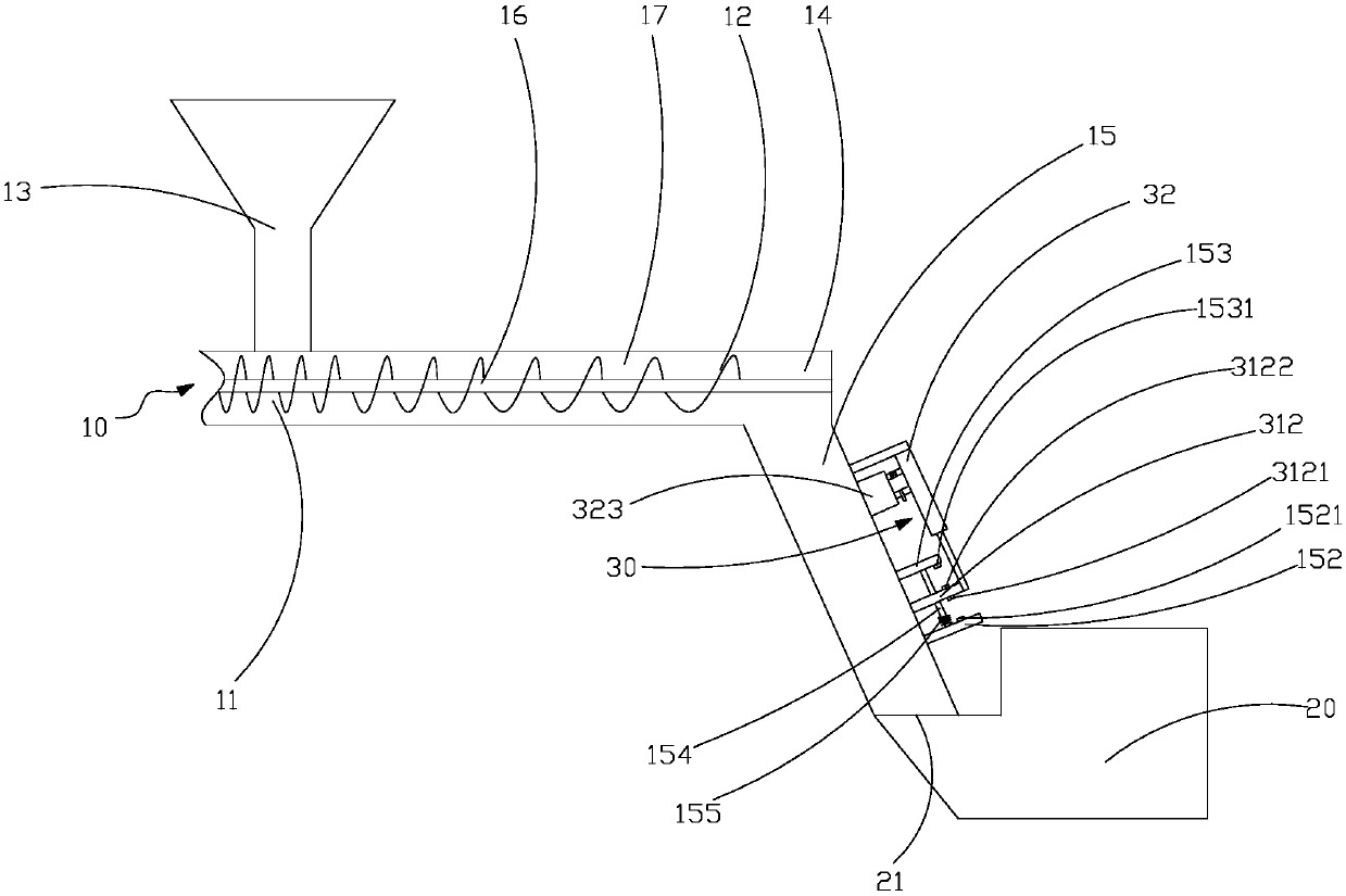
[0021] see figure 1 , the present invention provides a coal conveying device for conveying coal into a boiler 20 , the coal conveying device includes a screw conveyor 10 and an anti-blocking assembly 30 arranged between the screw conveyor 10 and the boiler 20 .
[0022] The opposite ends of the screw conveyor 10 are respectively provided with a feed end 11 and a discharge end 12, the top of the feed end 11 is provided with a lower hopper 13, the bottom of the discharge end 12 is provided with a discharge port 14, and the discharge port 14 There is a delivery pipeline 15 connected thereto. A screw 16 and a plurality of screw blades 17 arranged on the screw 16 are installed in t...
PUM
 Abstract
Description
Claims
Application Information