
A manual forklift with self-leveling function

A manual forklift, self-leveling technology, applied in the direction of the lifting device, etc., can solve the problems affecting the production efficiency of the stranded wire, the impact of the main shaft of the pay-off frame, and the non-level support surface of the forklift, so as to avoid the impact damage of the production equipment and ensure Structural stability, convenient and reliable effect

Active Publication Date: 2020-06-09
铜陵顶科线材有限公司
View PDF3 Cites 0 Cited by
  • Summary
  • Abstract
  • Description
  • Claims
  • Application Information

AI Technical Summary

Problems solved by technology

Because the wire reel is heavy and stuck between the two supporting claws of the forklift, if things go on like this, the front ends of the two supporting claws will be slightly separated, so that the center of gravity of the car body will be forward after the force is applied, and the front wheels will begin to deform and flatten, and the wear will accelerate, resulting in support Sinking phenomenon at the tip of the claw
Once the head ends of the two supporting claws of the above-mentioned forklift sink, it will cause the support surface of the forklift to be out of level, which in turn will cause the plate on the support surface of the forklift to be in a state of axis inclination
Obviously, the plate with inclined axis cannot smoothly penetrate the main shaft of the pay-off rack horizontally, and it will frequently collide with the main shaft of the pay-off rack or even get stuck, which will affect the production efficiency of the twisted wire at least, and cause damage due to impact. Cause the plate to fall from a height, resulting in production accidents

Method used


Image

  • A manual forklift with self-leveling function
  • A manual forklift with self-leveling function
  • A manual forklift with self-leveling function

Examples


Embodiment Construction

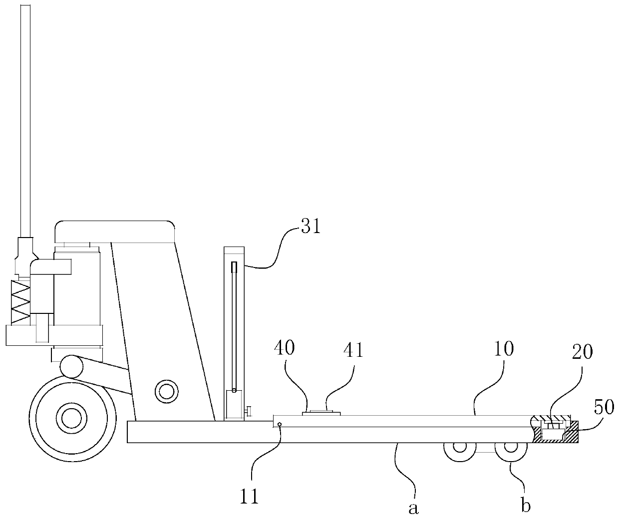
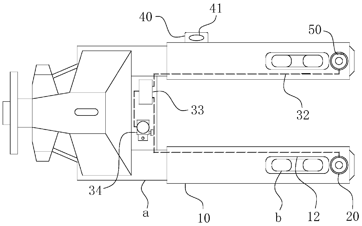
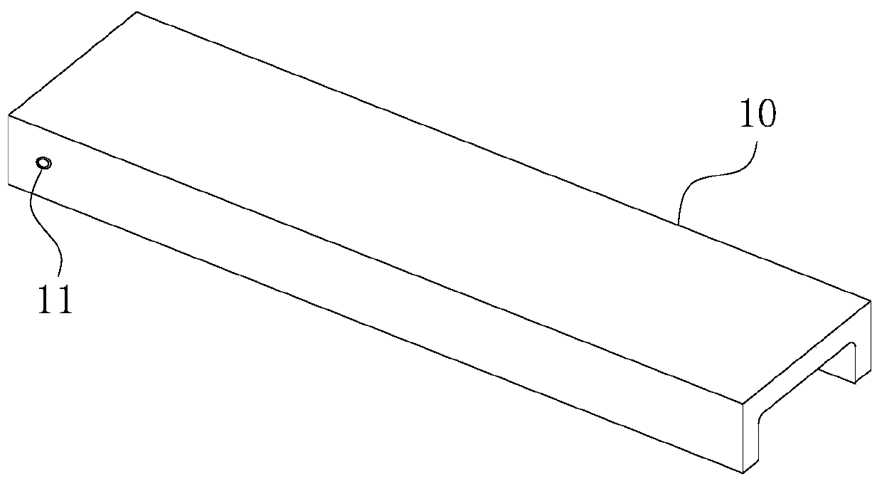
[0031] For ease of understanding, combined here Figure 1-3 , the concrete structure and working mode of the present invention are further described as follows:

[0032] The specific structure of the present invention is as Figure 1-3 As shown in the figure, its structure includes two sets of supporting claws a located in front of the vehicle body to carry the load. The two sets of supporting claws a are closed at the rear end and driven by the rollers at the rear end. Head end roller b.

[0033] On the basis of the above structure, the present invention also includes a movable support plate 10 buckled on the upper surface of the two sets of support claws a. Refer to the shape of movable support plate 10 image 3 As shown, it is a right-angled groove with the opening facing downward, and the groove width of the movable support plate 10 must be greater than the width of the corresponding support claw a, so that the movable support plate 10 can be used as figure 1 The one s...


PUM


Abstract

The invention belongs to the technical field of reel transportation and particularly relates to a manual forklift with a self-leveling function. The forklift comprises a movable supporting plate. Thetail end of the movable supporting plate and the tail ends of supporting claws form hinged fit, and the axis of a horizontal hinge shaft of the movable supporting plate and the supporting claws is vertically positioned on the axes of discs on the supporting claws. The forklift further comprises hydraulic jacks. The bottom ends of the hydraulic jacks are fixed to the front ends of the supporting claws, and the top ends of the hydraulic jacks vertically extend upwards and are supported at the lower plate surface of the head end of the movable supporting plate from bottom to top. The forklift further comprises a hydraulic assembly for driving the two groups of hydraulic jacks positioned at the front ends of the two supporting claws to generate synchronous lifting action, wherein the hydraulicassembly comprises a hydraulic pump, and the hydraulic pump is communicated with the two groups of hydraulic jacks through a hydraulic pipeline and an oil path distribution valve. By the adoption ofthe forklift, it can be simply and quickly ensured that the supporting surface of the forklift is in a horizontal state so as to ensure the reliability and efficiency of the penetrating action of thediscs relative to a main shaft of a pay-off rack.

Description

technical field [0001] The invention belongs to the technical field of coil transportation, and in particular relates to a manual forklift with a self-leveling function. Background technique [0002] During the production process of stranded wire, a manual hydraulic pallet forklift will be used to lift the reel containing hundreds of kilograms of copper wire and put it on the main shaft of the pay-off rack. Because the wire reel is heavy and stuck between the two supporting claws of the forklift, if things go on like this, the front ends of the two supporting claws will be slightly separated, so that the center of gravity of the car body will be forward after the force is applied, and the front wheels will begin to deform and flatten, and the wear will accelerate, resulting in support Sinking phenomenon at the tip of the claw. Once the head ends of the two supporting claws of the forklift sink, it will cause the support surface of the forklift to be non-level, and then caus...

Claims


Application Information

Patent Timeline
Patent Type & Authority Patents(China)
IPC IPC(8): B66F9/18B66F9/22
CPCB66F9/18B66F9/22
Inventor 陈鼎彪陈彬陈城曹永成黄亮汪洋孙玉好胡伯顺吴晓山张槐林吴智云黄爱军李齐靖秦磊王帮助查敏王建华
Owner 铜陵顶科线材有限公司
Learn More