A cashmere filling machine
A technology of a velvet filling machine and the other side, applied in the field of velvet filling machines, can solve the problems of not paying much attention to the fluffing work, no sterilization and smoothing, and no good treatment, so as to facilitate the filling work and reduce the Moisture, good air-drying effect
- Summary
- Abstract
- Description
- Claims
- Application Information
AI Technical Summary
Problems solved by technology
Method used
Image
Examples
Embodiment 1
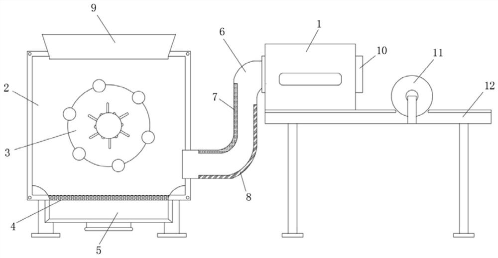
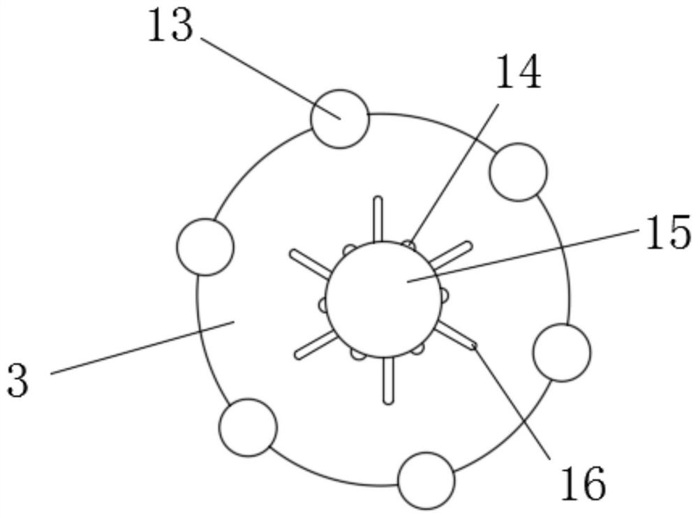
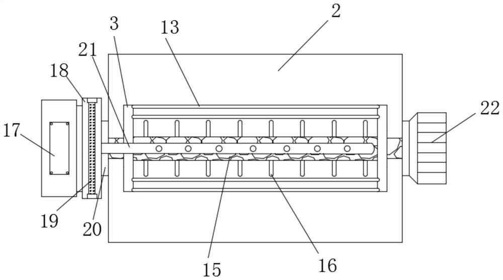
[0026] Such as Figure 1-3 As shown, a down filling machine includes a down filling machine main body 1, a pipe 6 is installed on one side of the down filling machine main body 1, and a down filling port 10 is installed on the other side of the down filling machine main body 1, the pipe 6 One end is equipped with casing 2, and described casing 2 top is inlaid with velvet inlet 9, and described casing 2 interior is provided with connecting disc 3, and described connecting circular plate 3 upper ring is provided with rubber band 13, and described connecting The inside of the circular plate 3 is inlaid with a connecting pipe 15, and the surface of the connecting pipe 15 is provided with a short rod 16 and a through hole 14. The through hole 14 and the short rod 16 are distributed in a cross manner, and the bottom of the box 2 is inlaid with a dust bag 5 A screen 4 is installed at one end of the dust bag 5, the box 2 is connected to the dust bag 5 through the screen 4, a bearing 2...
Embodiment 2
[0029] Such as image 3 As shown, a heating pipe 18 is installed on one side of the bearing 20, a heating rod 19 is clamped inside the heating pipe 18, a blower 17 is inlaid on the outer side of the heating pipe 18, and a blowing pipe is provided inside the connecting pipe 15. 21, the blowing pipe 21 is connected to the heating pipe 18 through the connecting disc 3 and the bearing 20, and the blower 17 communicates with the blowing pipe 21 through the heating pipe 18.
[0030] In this embodiment, when the blower 17 works, the heat in the heating pipe 18 can be blown into the casing 2 through the blowing pipe 21 through the through hole 14, which can play a very good air-drying effect and reduce the moisture contained in the fleece.
Embodiment 3
[0032] Such as figure 1 , Figure 4 with Figure 5 As shown, one side of the inner wall of the pipeline 6 is inlaid with an ultraviolet germicidal lamp 7, and the other side of the inner wall of the pipeline 6 is inlaid with an infrared ray germicidal lamp 8. The bottom of the main body 1 of the down filling machine is fixedly connected to the down filling platform 12, and the down filling One end of the upper part of the table 12 is equipped with a turntable 11, the turntable 11 is located on the outer side of the down filling machine main body 1, the upper ring of the turntable 11 is provided with a connecting rod 23, and the outer side of the turntable 11 is provided with a motor 24. The output shaft of the second motor 24 is connected to the turntable 11, and the two ends of the filling port 10 are welded with a rotating shaft 26, and a connecting column 28 is welded on the rotating shaft 26, and one end of the connecting column 28 is fixedly connected to the pressing pla...
PUM
 Abstract
Description
Claims
Application Information
 - R&D
- Intellectual Property
- Life Sciences
- Materials
- Tech Scout
- Unparalleled Data Quality
- Higher Quality Content
- 60% Fewer Hallucinations
Browse by: Latest US Patents, China's latest patents, Technical Efficacy Thesaurus, Application Domain, Technology Topic, Popular Technical Reports.
© 2025 PatSnap. All rights reserved.Legal|Privacy policy|Modern Slavery Act Transparency Statement|Sitemap|About US| Contact US: help@patsnap.com


