Waste mineral oil recovery and reutilization device with cleaning function

A waste mineral oil and functional technology, which is applied in the field of waste mineral oil recovery and reuse devices, can solve the problems of lack of cleaning mechanism, affect the filtering effect of the filter, and the inability to clean debris, etc., and achieve the effect of mixing evenly and preventing clogging

Active Publication Date: 2019-04-12
山东卓泰油脂科技有限公司
View PDF6 Cites 5 Cited by
  • Summary
  • Abstract
  • Description
  • Claims
  • Application Information

AI Technical Summary

Problems solved by technology

[0003] However, due to the lack of a corresponding cleaning mechanism in this waste mineral oil recovery and reuse device, the user cannot clean up the sundries accumulated on the filter screen, and the continuous accumulation of sundries will affect the filtering effect of the filter screen

Method used


Image

  • Waste mineral oil recovery and reutilization device with cleaning function
  • Waste mineral oil recovery and reutilization device with cleaning function
  • Waste mineral oil recovery and reutilization device with cleaning function

Examples


Embodiment 1

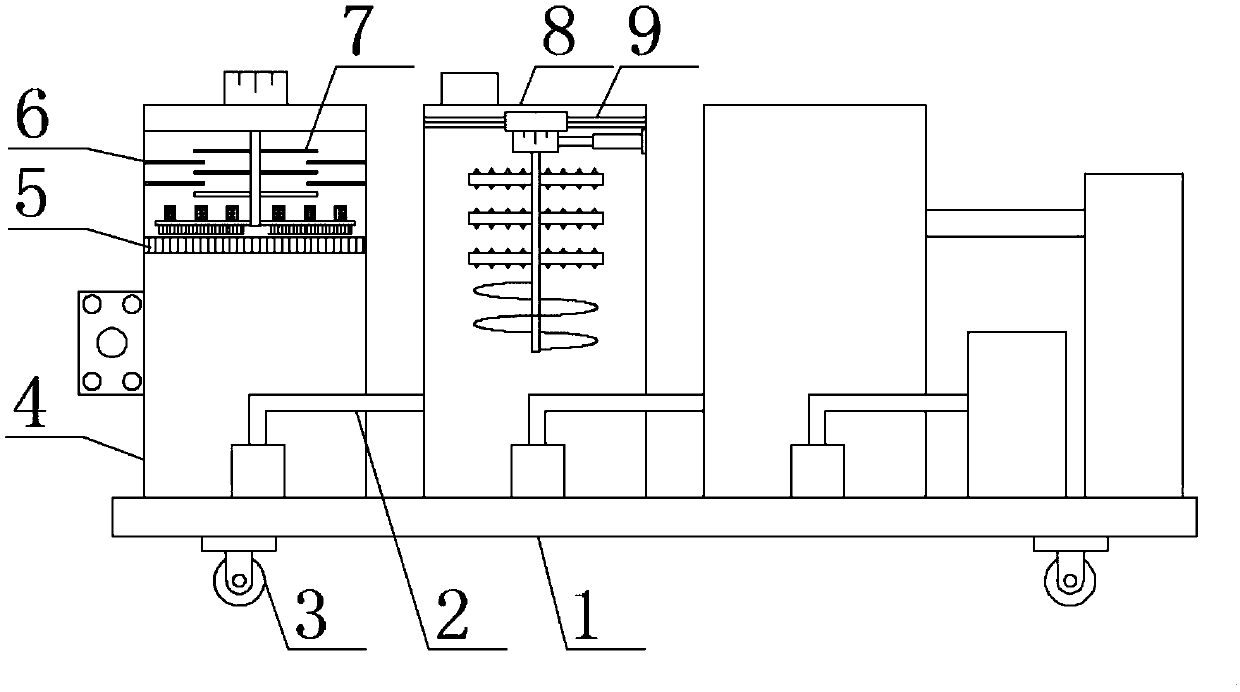
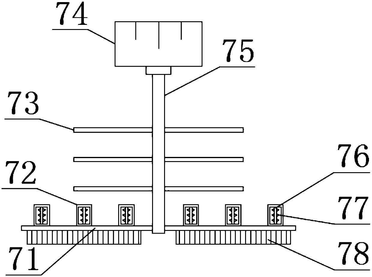
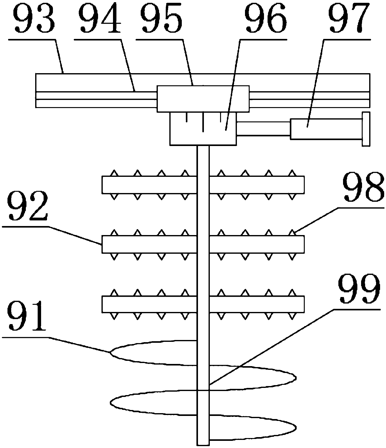
[0021] see figure 1 and figure 2 , the present invention provides a technical solution: a waste mineral oil recovery and reuse device with a cleaning function, comprising a support base plate 1, a cleaning mechanism 7 and a stirring mechanism 9, an oil storage tank 4 is arranged on one end of the upper surface of the support base plate 1, and supports The bottom plate 1 and the oil storage tank 4 are fixedly connected by welding, the top of the oil storage tank 4 is provided with a filter 5, one side of the oil storage tank 4 is provided with a stirring box 8, and the connection between the oil storage tank 4 and the stirring box 8 is provided with a first oil pipe 2. The stirring box 8 is fixedly connected to the support base plate 1 by welding, and the two ends of the lower surface of the support base plate 1 are provided with ground wheels 3. Mechanism 7, the top of the stirring box 8 is provided with a stirring mechanism 9, the cleaning mechanism 7 includes a first motor...

Embodiment 2

[0024] see figure 1 and figure 2 , the present invention provides a technical solution: a waste mineral oil recovery and reuse device with a cleaning function, comprising a support base plate 1, a cleaning mechanism 7 and a stirring mechanism 9, an oil storage tank 4 is arranged on one end of the upper surface of the support base plate 1, and supports The bottom plate 1 and the oil storage tank 4 are fixedly connected by welding, the top of the oil storage tank 4 is provided with a filter 5, one side of the oil storage tank 4 is provided with a stirring box 8, and the connection between the oil storage tank 4 and the stirring box 8 is provided with a first oil pipe 2. The stirring box 8 is fixedly connected to the support base plate 1 by welding, and the two ends of the lower surface of the support base plate 1 are provided with ground wheels 3. Mechanism 7, the top of the stirring box 8 is provided with a stirring mechanism 9, the cleaning mechanism 7 includes a first motor...


PUM


Abstract

The invention discloses a waste mineral oil recovery and reutilization device with a cleaning function, belonging to the technical field of waste treatment. The waste mineral oil recovery and reutilization device comprises a supporting base plate, a cleaning mechanism and a stirring mechanism, wherein one end of the upper surface of the supporting base plate is provided with an oil storage box; the supporting base plate and the oil storage box are fixedly connected in a welded manner; the top end of the oil storage box is provided with a filter net; one side of the oil storage box is providedwith a stirring box; the connection position of the oil storage box and the stirring box is provided with a first oil pipe; and the stirring box and the supporting base plate are fixedly connected ina welded manner. According to the invention, the cleaning mechanism is arranged on the waste mineral oil recovery and reutilization device, a user can remove foreign matters accumulated on the filternet through brush plates of the cleaning mechanism, so the foreign matters are prevented from continuous accumulation to affect the filtering effect of the filter net; moreover, the user can crush theforeign matters in the oil storage box through crushing cutters of the cleaning mechanism, so the filter net is prevented from generating blockage due to excessively large volume of the foreign matters.

Description

technical field [0001] The invention belongs to the technical field of waste treatment, and in particular relates to a waste mineral oil recovery and reuse device with cleaning function. Background technique [0002] Chinese patent (publication number is CN207944065U) discloses a waste mineral oil recovery and reuse device, including a base, an oil storage tank, a stirring tank, a separation tank, a light oil tank and a heavy oil tank are arranged on the upper end surface of the base, and the bottom of the oil storage tank is provided with There is a first oil pump, and the first oil pump is connected with a first oil pipe that passes through the oil storage tank and extends into the stirring box. A driving motor is arranged on the inner top of the stirring box, and the output shaft of the driving motor is fixedly connected with a stirring shaft. , the stirring shaft is provided with a plurality of stirring blades, the bottom of the stirring box is provided with a second oil...

Claims


Application Information

Patent Timeline
Patent Type & Authority Applications(China)
IPC IPC(8): C10G53/02B01F3/20B01F7/18B01F7/24B01F13/10B01F15/00B01D29/03B01D29/64B01D29/86B01D35/02B02C18/10B02C18/18B02C18/24B01F23/70
CPCB01D29/03B01D29/6415B01D29/86B01D35/02C10G53/02B02C18/10B02C18/18B02C18/24C10G2300/1007B01F23/70B01F23/708B01F27/1921B01F27/92B01F27/90B01F33/831B01F33/821B01F35/187
Inventor 黄冬艳
Owner 山东卓泰油脂科技有限公司
Why Eureka
Try Eureka