
Recycling treatment system for cutting fluid

A technology for processing systems and cutting fluids, which is applied in the direction of lubricating compositions, etc., can solve the problems of cutting fluid waste, decreased cooling and lubrication performance of cutting fluids, and increased costs, so as to reduce production costs, avoid odor and deterioration, and prolong service life Effect

Pending Publication Date: 2019-04-12
广东纳米德环保科技有限公司
View PDF10 Cites 0 Cited by
  • Summary
  • Abstract
  • Description
  • Claims
  • Application Information

AI Technical Summary

Problems solved by technology

The used cutting fluid is often mixed with chips falling from the workpiece, lubricating oil on the machine tool, grinding debris falling from the tool, dust in the environment, and decomposition products of the cutting fluid itself, etc., which eventually lead to deterioration and hair loss of the cutting fluid. Smell, the cooling and lubricating performance of cutting fluid decreases, but if the used cutting fluid is not recycled, it will cause a lot of waste of cutting fluid and increase the cost of production, so most enterprises will reuse the cutting fluid after treatment. The cutting fluid treatment equipment in the stage is relatively simple, and some equipment only have the function of solid-liquid separation, the treatment effect is poor, and the life of the cutting fluid is short

Method used


Image

  • Recycling treatment system for cutting fluid
  • Recycling treatment system for cutting fluid
  • Recycling treatment system for cutting fluid

Examples


Embodiment Construction

[0019] see figure 1 , a cutting fluid recycling treatment system of the present invention includes a solid-liquid separation tank 1, an oil-water separation device 2, a sterilization tank 3, and a filter tank 4 that are sequentially connected through pipelines. The solid-liquid separation tank 1 is connected with a sump 9, the sump 9 is used to collect, store and recycle cutting fluid to be processed, and a first delivery pump 10 and valve, open the valve, and the cutting fluid to be treated can be delivered to the solid-liquid separation tank 1 through the first delivery pump 10 .

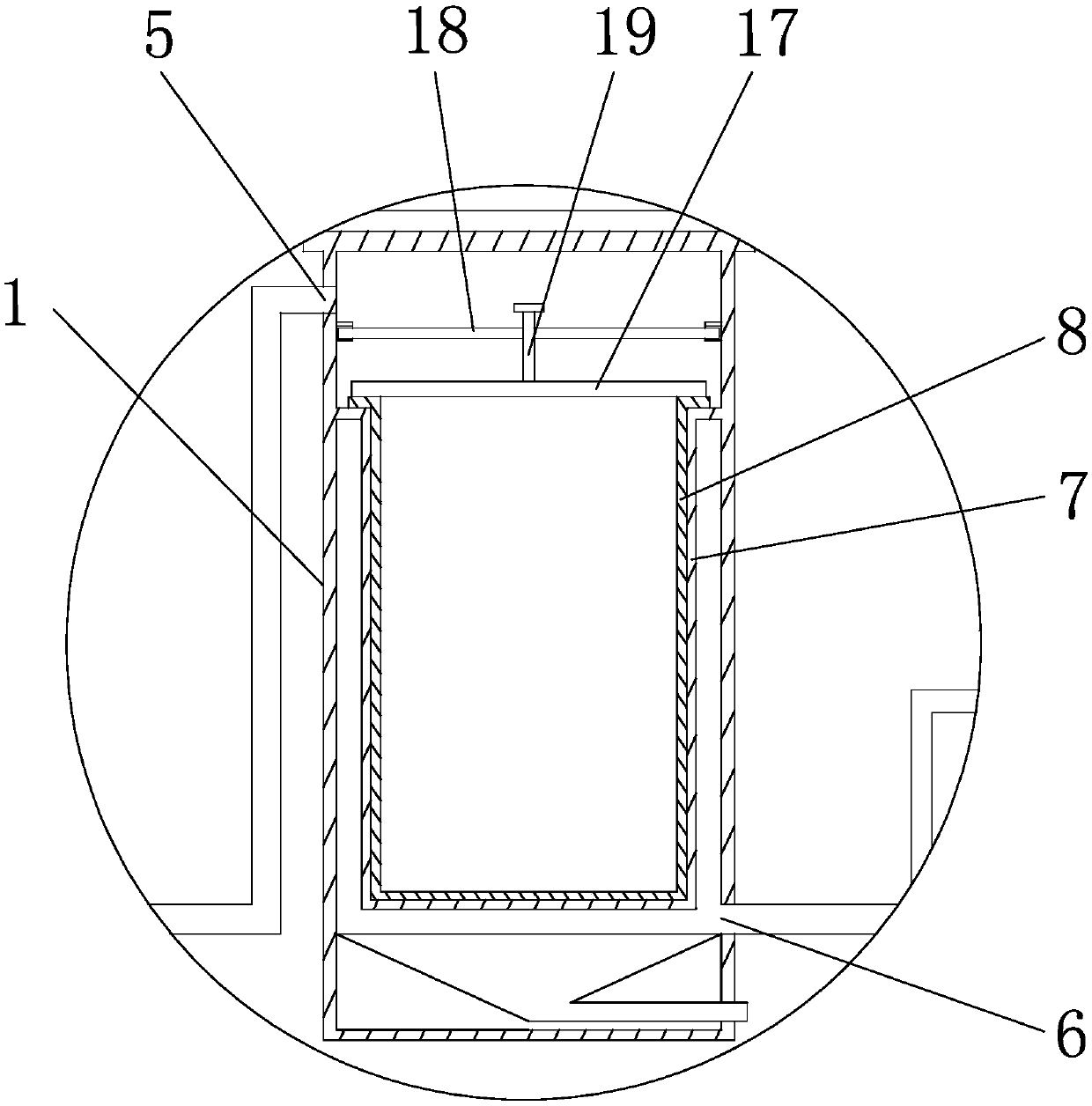
[0020] see figure 2 , the upper end of the solid-liquid separation tank 1 is provided with a liquid inlet 5, and the lower end is provided with a liquid outlet 6, and the solid-liquid separation tank 1 is provided with an annular protrusion along the circumference, and the protrusion is provided with an annular enclosure 7, an enclosure 7 The axis of the solid-liquid separation tank 1 can be pa...


PUM


Abstract

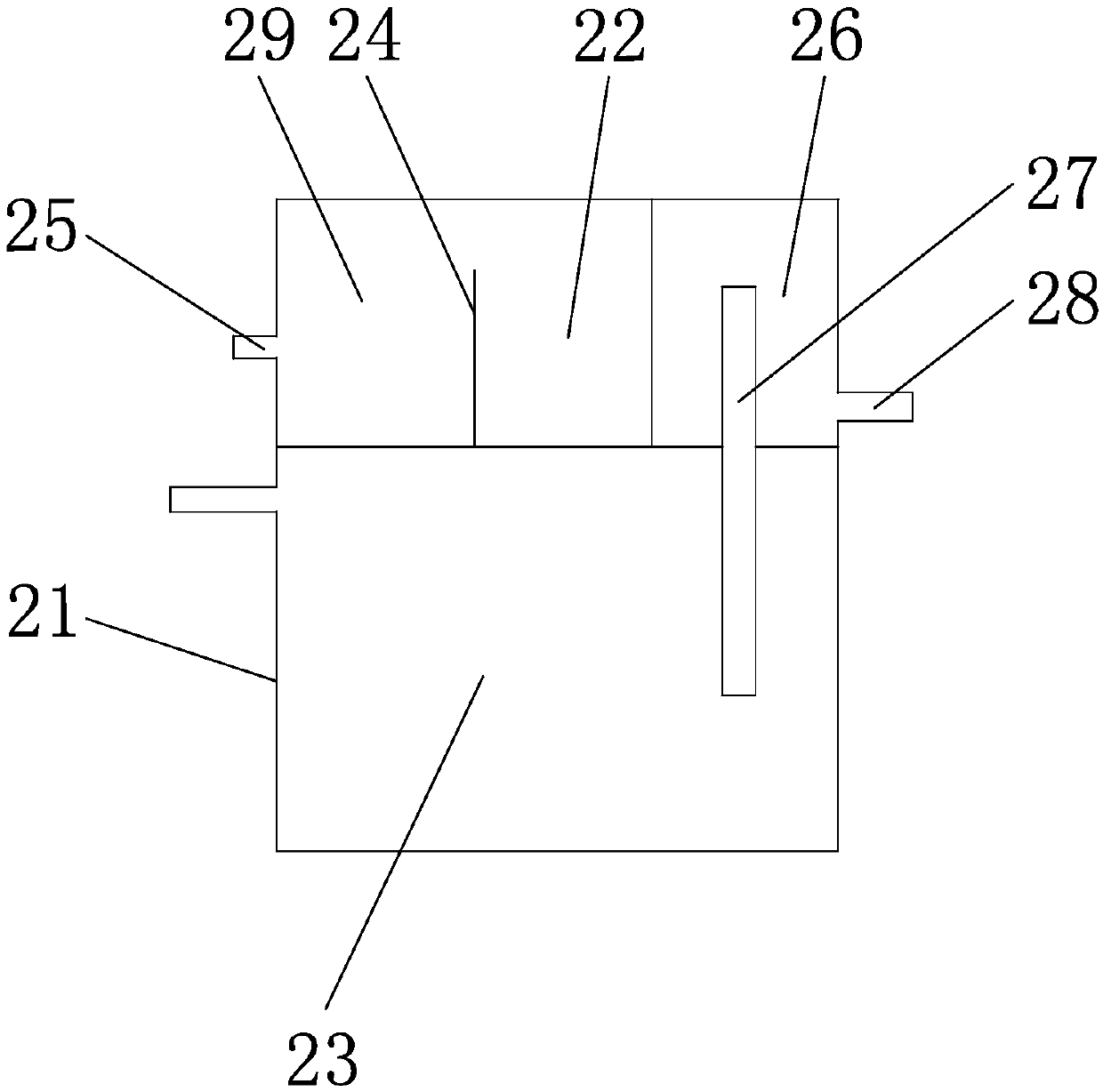
The invention discloses a recycling treatment system for cutting fluid. The recycling treatment system comprises a solid-liquid separation tank, an oil-water separation device, a sterilizing groove and a filtering tank which are communicated in sequence through a pipeline, a fluid inlet is formed in the upper end of the solid-liquid separation tank, a fluid outlet is formed in the lower end of thesolid-liquid separation tank, an annular protrusion is peripherally arranged in the solid-liquid separation tank and provided with an annular enclosure, the enclosure is provided with multiple through holes, a filtering string bag is arranged in the enclosure, the inner side region of the filtering string bag is communicated with the fluid inlet, the outer side region of the enclosure is communicated with the fluid outlet, a sterilizing device is arranged in the sterilizing groove, and a filtering membrane is arranged in the filtering tank. Through the filtering string bag, solid particles inthe cutting fluid are intercepted, the oil-water separation device separates out oil spill in the cutting fluid, the sterilizing device kills bacteria and fungi in the cutting fluid, the cutting fluid is prevented from stinking and going bad, and the filtering membrane filters ammonia-nitrogen compound and others in the cutting fluid so as to reduce COD; in this way, the excellent cutting fluid is obtained, the service life of the cutting fluid is prolonged, and production costs are lowered.

Description

technical field [0001] The invention relates to the technical field of cutting fluid treatment, in particular to a cutting fluid treatment system. Background technique [0002] When the machine tool is machining, in order to cool down the machine tool and the workpiece, and lubricate the machine tool and the workpiece, cutting fluid is often used, and a large amount of cutting fluid is sprayed on the tool and the workpiece. The used cutting fluid is often mixed with chips falling from the workpiece, lubricating oil on the machine tool, grinding debris falling from the tool, dust in the environment, and decomposition products of the cutting fluid itself, etc., which eventually lead to deterioration and hair loss of the cutting fluid. Smell, the cooling and lubricating performance of cutting fluid decreases, but if the used cutting fluid is not recycled, it will cause a lot of waste of cutting fluid and increase the cost of production, so most enterprises will reuse the cuttin...

Claims


Application Information

Patent Timeline
Patent Type & Authority Applications(China)
IPC IPC(8): C10M175/00
CPCC10M175/00
Inventor 周盛杰
Owner 广东纳米德环保科技有限公司
Learn More