
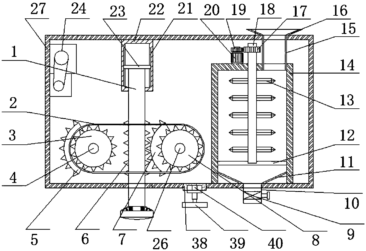
Bedding soil tamping device for construction site

A construction site and compacting device technology, applied in construction, roads, road repairs, etc., can solve the problems of unfavorable filling and compacting work efficiency, no filling and cushion, and inconvenient roadbed compaction, etc., and achieves a wide range of applications , prevent soil accumulation and improve the quality of roadbed

Inactive Publication Date: 2019-04-12
赵智慧
View PDF5 Cites 3 Cited by
  • Summary
  • Abstract
  • Description
  • Claims
  • Application Information

AI Technical Summary

Problems solved by technology

[0003] After searching, the Chinese patent application number is CN107476280A, which discloses a tamping device for municipal road leveling, including a tamping car body and a tamping device arranged on the left side of the tamping car body. The top of the tamping device is fixed with a right end and a The bulging portion fixedly connected to the top of the left side of the tamped car body is provided with a first cavity inside the bulged portion, and a second cavity is symmetrically arranged in the tamped car body on the right side of the first cavity. There is a connecting cavity between the two cavities, and the first guide wheel is connected with the rotation fit in the first cavity, but the tamping device for municipal road leveling above has the following deficiencies. function, which is not conducive to improving the work efficiency of filling and compacting the ground of the construction site, and the above-mentioned device is large in size and low in scope of use, which is not convenient for roadbed compaction on the construction site

Method used


Image

  • Bedding soil tamping device for construction site
  • Bedding soil tamping device for construction site
  • Bedding soil tamping device for construction site

Examples


Embodiment Construction

[0027] The following will clearly and completely describe the technical solutions in the embodiments of the present invention with reference to the accompanying drawings in the embodiments of the present invention. Obviously, the described embodiments are only some, not all, embodiments of the present invention.

[0028] In describing the present invention, it should be understood that the terms "upper", "lower", "front", "rear", "left", "right", "top", "bottom", "inner", " The orientation or positional relationship indicated by "outside", etc. is based on the orientation or positional relationship shown in the drawings, and is only for the convenience of describing the present invention and simplifying the description, rather than indicating or implying that the referred device or element must have a specific orientation, so as to Specific orientation configurations and operations, therefore, are not to be construed as limitations on the invention.

[0029] refer to Figure ...


PUM


Abstract

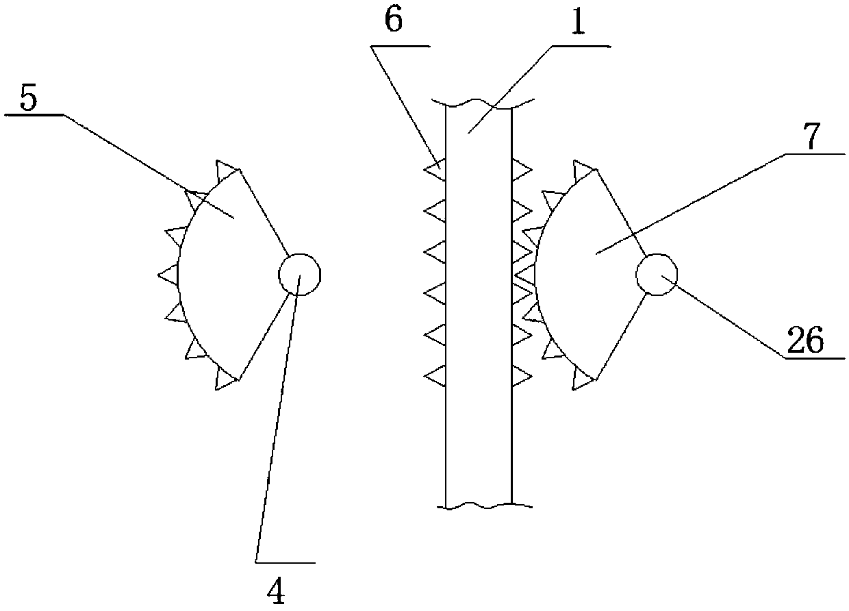
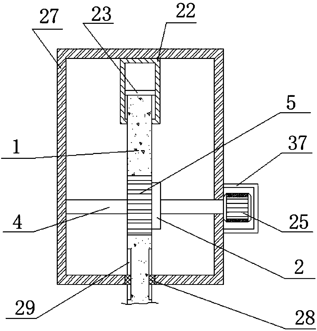
The invention, which belongs to the technical field of building construction, in particular relates to a bedding soil tamping device for a construction site, thereby solving a problem that the existing tamping device for flattening the municipal administration path does not have the functions of automatic filling and bedding. The tamping device comprises a mounting shell. A fixing cylinder is connected to the inner wall of one side of the top of the mounting shell by a bolt. First sliding slots are formed in the two sides of the fixing cylinder; a same horizontally arranged limiting rod is connected to the inner walls of the two sliding slots in a sliding manner; and the outer wall of the bottom of the limiting rod is connected with a support post by a bolt. A through hole is formed in theouter wall of one side of the bottom of the mounting shell; and limiting plates are connected to the inner walls of two ends of the through hole by bolts. According to the invention, with a servo motor, a driving gear, and a driven gear, tapered broken teeth on a rotating shaft are driven to make rotation and thus the soil entering a storing shell is smashed, so that the uneven roadbed can be filled with soil.

Description

technical field [0001] The invention relates to the technical field of building construction, in particular to a pad soil compacting device for a construction site. Background technique [0002] The construction site is a construction project under development. Ramping is a kind of construction operation that tamps the foundation or filled earth and rocks to prevent the ground from being soft and sunken, to ensure construction safety, and to improve its compactness. [0003] After searching, the Chinese patent application number is CN107476280A, which discloses a tamping device for municipal road leveling, including a tamping car body and a tamping device arranged on the left side of the tamping car body. The top of the tamping device is fixed with a right end and a The bulging portion fixedly connected to the top of the left side of the tamped car body is provided with a first cavity inside the bulged portion, and a second cavity is symmetrically arranged in the tamped car ...

Claims


Application Information

Patent Timeline
IPC IPC(8): E01C19/46E01C19/48
CPCE01C19/466E01C19/4833
Inventor 赵智慧
Owner 赵智慧
Learn More